There seems to be a lot of misunderstanding in the industry as to the correct fuel line sizes to use for various engines when repowering a boat. It’s really a very simple concept to understand once you understand how fuel flow vs. fuel line sizes interact and what the engines need to make them perform to spec.
Because of the popularity the 6 cylinder 6BTA or 6CTA Cummins (not that it really matters), we’ll use these engines as a basis for this discussion. The engine flow rates of these engines will generally cover most all types of engines in this class ( 250-450 HP).
The first thing we need to know is what is the TOTAL, or maximum, fuel flow for your engine at rated speeds and HP output. In this case, and most any 250-450 HP 6 cylinder diesel that uses an ND EP-9 type or Bosch P7100 fuel injection pump (or a system of similar design), just assume the fuel flow is about 1 GPM. Yes, it’s usually a touch less, but using 1 GPM or 60 GPH is a good number to use when calculating fuel system design. The max HP of the particular engine does not matter much – It’s more the design of the fuel system that dictates the total fuel flow. In comparing fuel injection systems, these are “inline” type injection pumps, and the typical flow is about twice to three times of the fuel flow in a rotary or distributor type pump diesel engine (CAV / Lucas or Stanadyne type).
Next, we need to know the factory’s maximum values, numbers, or pressure drops that the engine can tolerate to work properly for both the supply side (suction) and the return side (restriction-pressure of the return line). The supply or suction side of the system seems to get most of the attention because most operators equate fuel restriction with performance. Yes, you can equate the two but not as most think. We’ll get to that later as that is a slightly different subject.
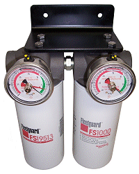
Fuel supply restriction or “pressure drop” is always measured as a negative number because it is on the suction side of the fuel lift or supply pump. Units of measurement can vary, but inches of Mercury (Hg) seems to be most accepted. Regardless of the units of measure used, fuel restriction values need to be very low, and in a general sense, the lower the better when the system is fresh or new as this gives the operator more time between filter maintenance. Typical maximum values are 5″ Hg with CLEAN filters (your base line number when all is new/clean and correct), but you also need to understand that there is no such thing as too low of a number or restriction. Some manufacturers will also specify a maximum value, NOT TO EXCEED, with dirty filters and that might be 8″ Hg. Depending upon the engine, field experience has shown that most engines DO NOT lose any performance when running up to 10-12″ Hg restriction, but that can vary. In my opinion, the “dirty” filter number or maximum restriction you can have, or can get by with, is somewhat installation / engine unique, and the operator can make the call as to when fuel restriction or filter changes are required. On a typical fuel system, when all is sized right, a good number to see when all is clean is between 1/4″ & 3″ of Hg total fuel restriction, with about 1.0 to 2″ Hg most common in a well designed fuel system. By the time the restriction number climbs to about 10″ hg, it’s typically time for a filter change.
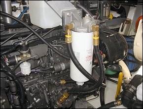
Fuel return line pressures are also something that needs to be considered in the design of a fuel system. Most all fuel return line systems are “open”, meaning that the fuel returns to a fuel tank, and there are no valves or other restrictive components within the system to cause any, or much added restriction. Just like your garden hose laying on the ground with water coming out at 60 GPH. So, where could the restriction come from, you ask? Some may come from an inline return fuel cooler (not much if they are sized right) and friction inside the fuel line with fuel flowing thru it, which brings us to what this discussion is about – Fuel Line Restriction, and how it interacts or affects overall fuel restriction on both the supply and the return fuel system on a diesel engine. Just about everybody seems to equate fuel restriction with the fuel filtration system and it’s design, and never thinks about the fuel line as being a major factor in this equation, even when all is new and clean. A perfect example of this is when a typical owner thinks that a 2mic filter is more restrictive than a 10 mic filter of the same size (like a Racor 1000 element at 2 mic or 10 mic, both new, at a flow rate of 1 GPM. In actuality, both elements would be under .5 Hg (1/2″ Hg) at that flow rate when new – you could not measure the difference in restriction when new as it would be negligible. Yes, the 2 mic will load quicker (get dirty) and the restriction would rise faster, but isn’t that what it should do?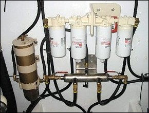
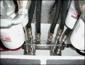
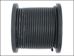
But, here is what all seem to not realize. Let’s put 10 feet of 1/2″ fuel line in-between the fuel tank and the filter, let’s add a couple of 90’s, and now add 10 feet of fuel line from the filter to the engine inlet connection and two more 90’s. Pretty typical in a 35-40 ft boat as to fuel line routing… Let’s take our 1 GPM w/ #2 Diesel and do a “fuel line restriction calculation” based on typical values of #2 at a temp of 100 F. I’ll use a specific gravity of .85 and a viscosity of 3.0 centipoises (these would be reasonable numbers). We just ended up w/ a .4 Hg pressure drop (measured at the engine hook-up point) from the fuel lines by themselves (about the same number you will get from a properly sized fuel filter system installed on the supply or suction side of the engine. This would be about normal. Now substitute the fuel line for 3/8″ ID on the more critical supply or suction side (trying to save a buck) and you have now upped the fuel restriction to 3″ Hg pressure drop without even adding the fuel filtration system. Inside the ½” fuel line the fuel would be traveling at 2 ft/second and inside the 3/8″ fuel line just over 3 ft per second. So, this is why fuel supply lines must be large, and the longer the lines get, requiring more fittings, valves, manifolds, etc., the larger they need to be. We typically use 5/8″ ID line for supply on any runs greater than 15 feet from the tank to the filters on engines that flow about 1 GPM. Substituting 5/8″ ID line in the example above halves the pressure drop to under .2 Hg. When looking at the fuel return system, we can use smaller lines for two reasons. One, the maximum allowed value for the pressure drop is usually 2-4 times more and the return flow is always less (at least to some extent) than the total fuel flow. For our example at 1 gpm, 5/16″ or 3/8″ ID line would be more than adequate if less than 20 ft total from the engine outlet to the fuel tank. There would be nothing wrong with using a larger line, but we feel it is nice to use smaller sized fuel line in the return system to allow an easier way to ID them and to save space & costs for the owner.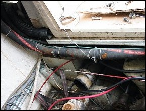
In closing, remember that you not only have to think “fuel filters” when pondering your fuel supply system design if trying to keep “restriction” at the minimum.. Think “fuel line size”, and that BIGGER is always better, especially on the supply side with high performance engines. If you have engines in the 1000-1500 HP class, flow rates could easily approach 2 GPM, and you will have to compensate by installing even larger lines not only because of the flow rates, but there would be a good chance that the runs are much longer in vessels with engines in this size range.