Introduction
 Back in the 1970’s I became heavily involved in the mechanics of boats and before I knew it they became my passion. I have been lucky to have gained over 25 years of experience and 10’s of thousands of engine operational hours (300+ diesel engine installs) and have learned (sometimes the hard way) what it takes to make a reliable engine / power train system, and all that that incorporates. The Marine Exhaust System is a major part of this.
My hopes are that the information in this article will shed some new light on the understanding (and misunderstanding) of one of the most important aspects of a successful boating experience: The Marine Exhaust System.
An important goal here is to remove some of the mystery surrounding much of the misguided and ill conceived “couch engineering” designs that have been imbedded in the boating industry for far too long. Some common sense is the first part that is needed to design a safe and reliable exhaust set up. And, the key word here is “GRAVITY.” Just putting some thought into the general placement of your exhaust system, and with the knowledge that I hope you glean from this article, should help solve many, many horror scenarios down the road. Also remember this (something you can take to the bank), doing it right the first time will leave your wallet much more in tact in the years that follow.
It has been a few years since I posted some thoughts, pictures and politics on Marine Exhaust Systems, so it is time to update. And, since exhaust system design, fabrication, and installation have become a large part of our business, the time is here to share some of what we have learned over the past two decades in this ever changing business.
First and Foremost
The two most basic issues that need to be understood and accomplished:
- A safe system for both the boat, on board personnel and the engine, it needs to be long lived & must meet manufacturers’ requirements as to back pressure and water entry.
- The exhaust design and/or system must fit the boat and work in such a way that water will never flood the engine, even if something fails, and the system needs to look “politically correct”.
To this very day, much of our work still involves replacing, rebuilding, or repairing engines solely because of a poorly designed and/or fabricated wet exhaust system that allowed salt water into an engine’s internal workings. Seems the most basic of all natural forces in our lives, “GRAVITY,” was “left out” of the design process, and then, mixing that with couch engineering and “back yard designers,” you now have a recipe for disaster someplace down the road, sometimes very soon after you purchase a new boat.
Exhaust Size
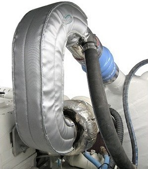
Let’s start our main discussions with exhaust sizes (NOT overall design, as we must first figure out what is required to meet engine requirements), dissect them a touch, and then decide what is needed and what will work. You must also understand that when we talk “marine exhaust” we are usually talking a “wet” system, but also realize that inside this “wet system” we have two distinct parts. In most exhaust systems that are in the type of boats discussed in these forums (150-800 HP diesel engines), there are TWO distinct parts of the exhaust system/piping. The DRY part and the WET part. Even on the factory supplied 90 degree “wet elbow,” these two sections exist, though many people don’t realize it.
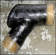
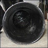
The inner pipe of this “wet elbow” is actually/usually a 90-degree dry bend, or section, surrounded by raw water to keep the surface cool. At the end of this “wet” elbow, where the exhaust hose attaches, is where the water is introduced (hence the term “mixing elbow”) and the exhaust NOW becomes wet. Inside this elbow is a smaller diameter (typically around 2 ½ – 6″ ID) which is the dry side, and where the hose attaches (it expands to (or is surrounded by) 4-10″ tubing/OD piping, depending on the engine size, etc.)
EXHAUST SIZE can be determined by a few rules, but all really come down to two things:
#1 – Meeting the engine requirements as to total restriction (back pressure). #2 – Designing a system that will FIT inside the boat’s constraints.
Most Important Point to Understand:
Very simple, if you can’t meet Rule #1 and Rule #2, then nothing else matters and the exhaust is the WRONG SIZE. One, it won’t meet engine specifications / requirements, and two, it won’t fit within the constraints of the boat.
As to meeting engine/manufacturers’ requirements regarding “back pressure,” this is where it is so vital to select the correct sizes of piping & mufflers, design the actual layout or flow path, and then put it all together so exhaust flow is not allowed to build up over this maximum pressure limit assuring safety in all aspects related to the installation.
Exhaust back pressure measurements are a very low number, something like what it takes to blow up a balloon. The pressure is usually measured in units of Water Column Height or Mercury (Hg). Typical maximum limits are from 1.5″ Hg to 3″ Hg or 20″ to 40″ of water (right around 1 PSI), depending upon the manufacturer. John Deere, Lugger and Detroit seem to want back pressure lower (about 30″ water max) than Cummins or Yanmar (40″ to 50″ water), and this makes it even tougher to meet the requirements and build a system that will fit. A new specification for exhaust back pressure limit from Cummins for the QSB was just released that will easily allow a well designed 5″ WET system to meet back pressure requirements on the QSB 380 and possibly even the newest 480 version if a well thought out design is used. Cummins now allows 5″ Hg (about 2.45 PSI-68″ of water column) on all the QSB’s. This is a very friendly spec and can make for a much easier and less expensive exhaust system installation.
But, back to sizing. Exhaust flow is determined from the amount of HP the engine makes and the more HP, the more exhaust flow; therefore it will take larger piping and/or less bends, shorter lengths etc., to meet back pressure requirements. Also, a very simple to understand concept (even though most installers seem to forget) is the “bend” equation part of planning an exhaust. Figure a smooth radius 90 degree bend is equal to about 6-10 FT of DRY piping and 15 FT of wet piping. Another good rule of thumb to remember is for every 100 PRODUCED horsepower, the engine makes about 200 CFM of exhaust gases, but this does not include the water and / or steam that becomes part of the mix when water is introduced. That’s why dry piping can be smaller than wet piping, WATER and steam add to the total flow in a substantial manner; therefore once water is introduced, the piping MUST BE LARGER.
Past experience as to what size will work and meet requirements is always a plus when in the initial planning. But not all are so lucky, so they turn to the engine specs or installation guide and see what is “recommended,” and/or they use the factory supplied wet elbow size to go by. In some cases this is fine and gets you by with the least amount of cost and effort. In most cases, the hose size that fits the factory elbows will work in 90% or more of the applications out there.
Below are some notes on 3 most common WET exhaust sizes that have shown to meet all restriction requirements for Cummins engines over the last 20 years and are based upon well over 300 Installation Reviews and exhaust tests. Keep in mind that the dry section and wet section are different and must be treated so. Also take into consideration the type of muffler, the overall length of the system, the amount of both dry and wet bends, the amount of water that you inject into the system (some of it, if not all of it), the angle of the discharge AFTER you inject water and how the system exits the vessel. All of these affect the total system back pressure. I am using Cummins engines as that is what most of my experience is with and I am using 3″ Hg or 41″ of water column as the maximum back pressure limit:
Learn to understand the nomenclature difference between “pipe,” “tube” and “hose” dimensions.
For this discussion, pipe size is always shown as a nominal size in SCH 10 wall ( .120″-ish) – I.E.
- 2.5″ = 2 7/8″ OD
- 3″ = 3.5″ OD
- 4″ = 4.5″ OD
- 6″ = 6 5/8″ OD
“Wet” size is always the actual ID of the exhaust hose. Tube is always the actual OD of the tube (pipe) and is usually about 1/8″ wall meaning a 5″ WET tube or FRP (fiberglass) exhaust tube or pipe has approx a 4 ¾” ID.
Exhaust hose (any hose for that matter) is always sized as an ID measurement and always is sized to FIT OVER a tube OD dimension or pipe outer diameter measurement.
4″ Tube, 4″ pipe size ( 4.5″ OD) & 5″ WET SYSTEMS – 6BT 210, early 6BTA’s – ( 200-250 HP) Factory recommendation is 5″ WET (Yanmar 6YLA too), or most any diesel in between 180 and 250 HP.
Experience has shown that 2.5″ pipe (2.875 OD) for a short length or one “90,” OR 3″ pipe size ( 2-3 90’s) for the dry section, and 4″ tube to 4″ pipe for the wet section and wet muffler is usually fine. This would also apply to a 4LHA 240 Yanmar and 6LPA 315.
6″ WET SYSTEMS – 6BTA’s – 300 ~ 370 Diamonds and QSB’s thru 480’s, QSC’s , QSL’s ( 300-500 HP) – Factory recommendation is 6″ wet.
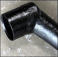
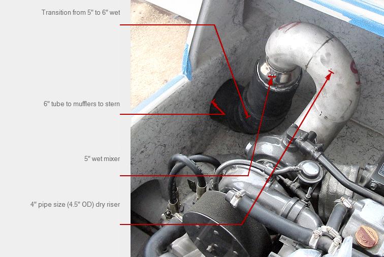
Well, this is where we have some “fudge factor” if you want to design it right and make it “fit” the boat. Going from a 5″ wet to a 6″ wet ( typically in 300-450+ HP engines ) is HUGE and opens many install capabilities. We like 6″ mufflers and piping from the typical engine room bulkhead aft to the exit near or at the stern. But we like to do our engine risers/custom elbows and wet mixers in 4″ pipe for the dry section and 5″ WET outlets where space is an issue. Using a properly designed dry riser w/ a 5″ mixing elbow, and then transitioning to 6″ at the engine room bulkhead, saves valuable space in smaller engine rooms, saves money for the customer, and is just about always easier and a better overall and “politically cleaner” install. The transition from 5″ to 6″ wet is always easy as 5″ to 6″ FRP tube is an easy make for a custom elbow of any degree at 45 or less. If a highly restrictive muffler is used, or the available space allows the use of 6″ close to the engine, then a 6″ mixer might be the best choice.
8″ WET SYSTEMS – Some “C” & QSC installs, QSM’s-400++ to 800-ish HP-Cummins has “recommended” both 6″ and 8″ and seems wishy-washy on this.
Well, I have yet to see a C, QSC, QSM, or any Cummins (or other make) engine UNDER 500 HP need an 8″ wet exhaust system to meet specs. But, I continue to see this as a RECOMMENDATION for the exhaust size in many cases. I guess if you have the room, the budget, and have an extraordinary amount of bends and/or an overly restrictive muffler, then maybe you should go for it. But from a vast amount of experience, we always stay with 6″ max if under 500 HP.
When we get up into the 500 – 800 HP-ish HP range, this is when we need to think about some, or all, of our WET side of the system being 8″. Since most of my work and the discussions on this site center around repowers of sportfishing boats like Bertrams, Vikings, Hatteras, etc, let’s confine the 8″ to this general style of boat in the 40-60 ft length range. And, with so many older Detroit powered boats/owners still out there that are now seriously looking at repowers, and most of these having 8-71’s , 6-92’s, 8-92’s, etc., this is now even more important to understand.
Usually, these boats have 8″ or even 10″ WET systems aft of the engine room. This is typically where the mufflers are located too. If all is good aft of the engine room – all piping, mufflers, outlets and hoses – (it is usually not), then this is a good size to start with for adapting to the newer 4-stroke engine. If some or most of this piping needs to be replaced because of age, it’s usually easier just to stay with the same size for the section aft of the engine room. If you’d like to size down for space or cost reasons, then a good look at the overall system and engine requirements will be needed.
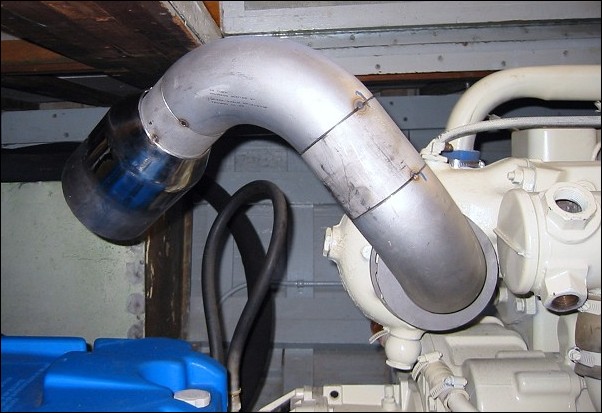
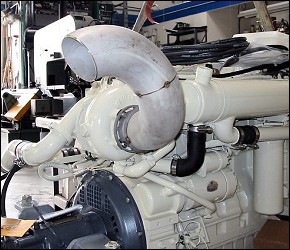
Let’s look at a new QSM at 670 HP as to what will easily meet the spec. The factory supplies an 8″ fabricated wet elbow or mixer and IMO is of questionable use or quality. Yes, they do work in many applications when used correctly, but also seem to be subject to both internal and external leaks before their time because of the many welds and thin wall construction. Even worse, though, are the “installers” who re-weld or bolt these units in a dangerous “up” orientation in order to build a cheap “Mickey Mouse” type riser. I not only see this with the QSM’s but also in many other installs using the factory 5″ and 6″ “factory” wet elbows.
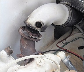
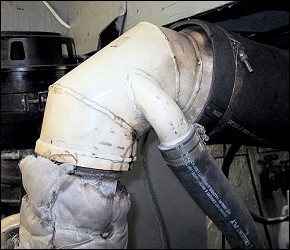
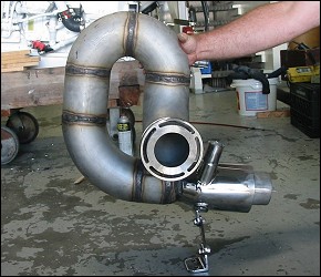
For those who cannot grasp what the issue is here, a simple explanation – This is a double walled 90 degree wet elbow that was never designed to “hold water” in this orientation but, rather, be mounted horizontally so as to exit downhill and self drain. When installed like this, the sea water that will eventually corrode thru the elbow will now go down the pipe into the turbo or worse. I hope you do not recognize this type of system on your boat!
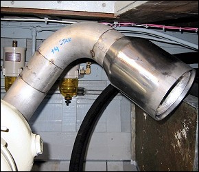
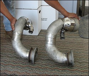
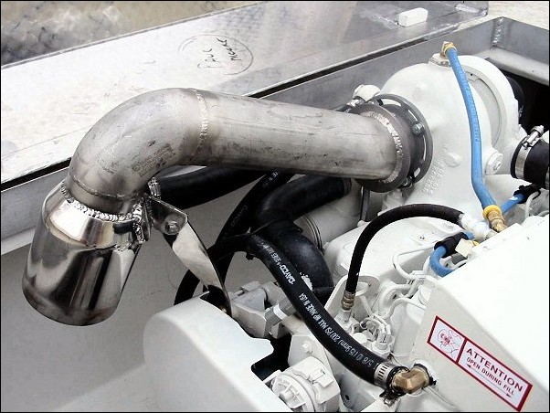
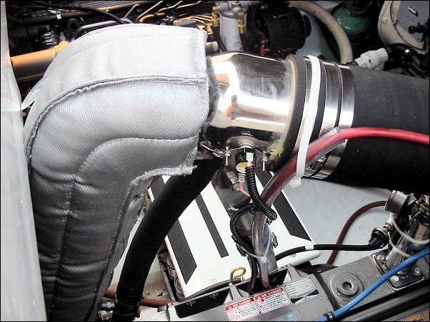
Now, back to 8″ – This is what we have found with engines in the 600-700 HP range as to designing a wet exhaust system and working around the existing 8″ – 10″ piping or “book” recommendations. We typically use 4″ dry piping from the engine up to a well designed 6″ wet mixer. This usually includes 3 to 4 pieces of 4″ pipe size “weld” 90 degree dry elbows and then a double walled wet mixer of our design orientated on the downhill side of the system. The mixer is always pointed to a spot on the vessel so we DO NOT have to incorporate any WET bends / “90’s”, etc., BEFORE the transition to 8″ (or 10″) from the engine room aft.
With good design and thought, along with some first class fabrication, meeting exhaust restriction requirements can easily be done with a mix of both 4″ dry, 6″ and 8″ wet which will make for a much cleaner install while making the engine room more user friendly as to maintenance, etc.
To recap, exhaust size is something that can be adjusted to not only meet requirements for the engine, but also fit the vessel’s constraints. When sizing the system to meet acceptable restriction requirements in order to protect the engine from excessive back pressure, keep bends to a minimum, especially “wet” 90 degree bends. With some planning, most exhaust routing designs can eliminate a one or two 90 degree bends by building a custom riser/mixer and make for a less restrictive, less cumbersome and safer exhaust system.
Summary
In closing, please understand that with some good engineering and thought, a well designed exhaust system can make a big difference in the layout of the engine room and offer a superior design as to safety and functionality. The idea that rarely a month goes by without our shop seeing a disaster from water ruining an engine from a “factory” type exhaust system or from an OEM builder with his head between his legs still befuddles me. To this day I see drawings from architects who have no clue. The drawing below is from a boat being built that is just such – All that height in the engine room and the architect has the system riser backwards – Just ask yourself what would happen while cranking the engine when out of fuel. And just as bad is that he got paid to design it this way. Sad, very sad…….
Marine Exhaust systems are one of the more important construction features on a vessel. Done wrong they are not only a safety issue for the passengers and the vessel, they can also lead to premature engine failure and / or indirectly cause poor maintenance to be performed on a vessel because of lack of design thought in the engine room. So many times when the exhaust design is an “afterthought,” normal or routine maintenance is close to impossible.
If you give this some thought in the future, maybe this will help you in your next repower or new boat design – The energy that a typical 400 Hp diesel puts into the propeller is matched close to 100% by the energy that goes out the exhaust system. So if you think your power train needs to be well designed, don’t cut any corners on the exhaust design – It needs to be just as tough and built with the same degree of design to handle that kind of energy.
Hopefully the pictures and design ideas incorporated here will help remove some of the mystery in exhaust design that seems to elude much of the industry. I fully understand that a buyer of a new boat does not have much input as to exhaust design when purchasing a new or used vessel, but we hope the guidelines here help not only the buyer to understand what to look for in a boat, but also will prove to be beneficial to the builders in the design and planning phase of marine engine rooms.