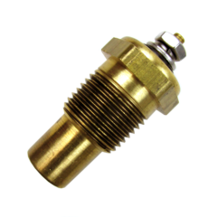
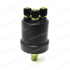
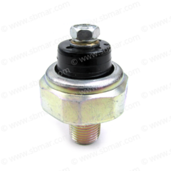
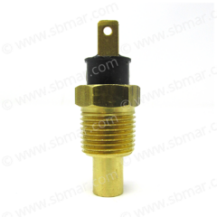
Many Photo and Research Credits go to: Rob Schepis
Overview
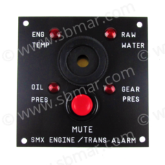
Many things can go wrong in a marine environment and more often than not typically do in the worst way… and without a robust independent alarm indication system, missed events turn catastrophic and can be VERY costly. Do you really want to leave your alarming and fault indication up to a single and sometimes unreliable source? In my opinion, the cheapest and most reliable system is to supplement the engines existing instrumentation and alarm systems with a simple, independent alarm circuit that leverages a small collection of alarm switches, buzzers, and lamps. The goal being an easy to recognize indication of which fault is being presented and a buzzer and/or lamp that is both loud and bright enough to grab your attention while focusing on piloting the vessel under way. Many companies even offer panels that allow indication of multiple faults on one easy to see panel. This eliminates having to take up valuable dash space with more than one buzzer, lamp, etc.
Alarming Terms
Sending Unit vs. Switch:
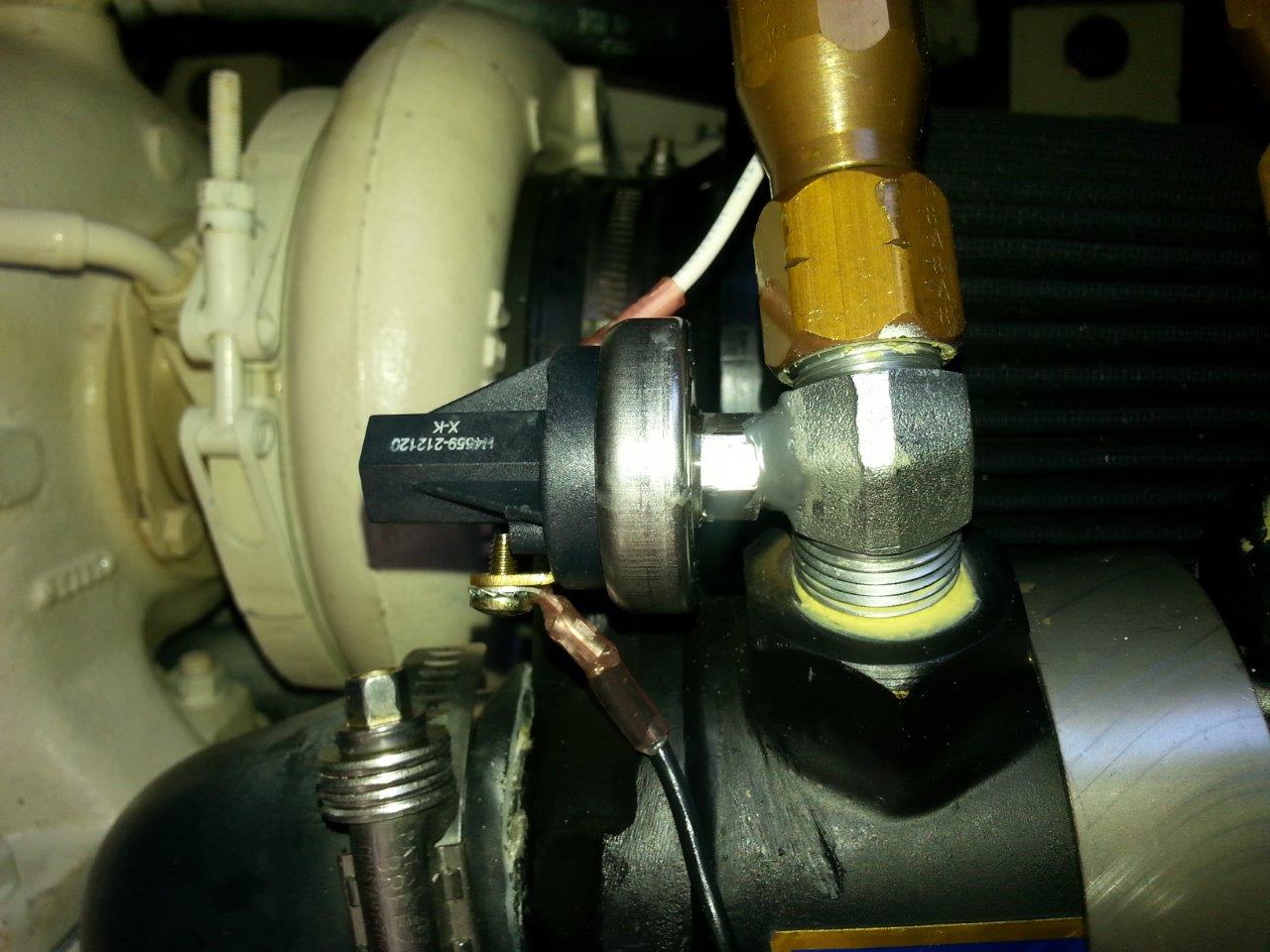
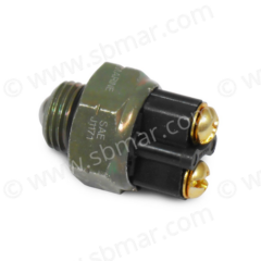
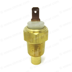
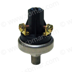
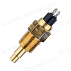
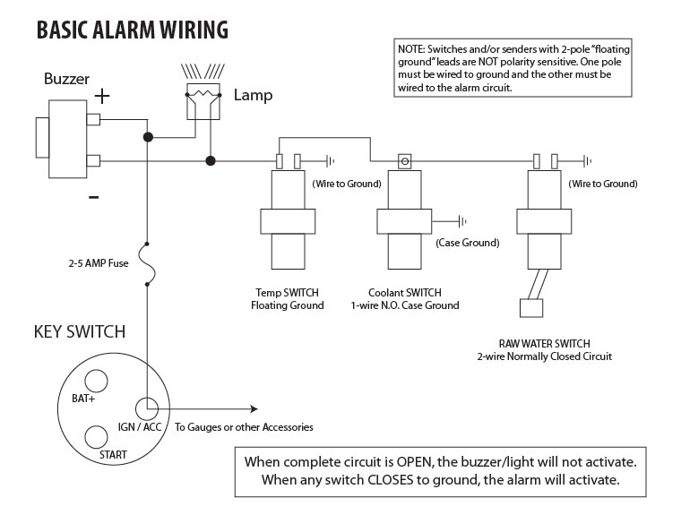
A sending unit and a switch look the same but have different functions. The sending unit changes resistance with changes in temp or pressure and the resistance is used to control a gauge of a preset range. The switch is a similar looking device but it is either “open” or “closed” or for a better word association with it’s name, it’s either “on” or “off.” When the switch is closed (on) it is making connection to ground which completes the
12V alarm circuit.
Normally Open (NO):
A normally open switch does not make contact or complete the circuit when it’s in the “normal” state, such as holding it in your hand or in an engine at rest. If you put a continuity meter from it’s terminal to it’s body (or second terminal, depending on the switch type) there will be no continuity. The switch will close when the switch reaches it’s set point, such as a 205 deg F coolant temp switch at 205 deg F or higher. NO switches will not activate the buzzer/lamp when the ignition is keyed on.
Normally Closed (NC):
A normally closed switch is making contact or completing the circuit when it’s in the “normal” state. If you put a continuity meter from it’s terminal to it’s body (or second terminal) there will be continuity. The switch will open when the switch reaches it’s set point, such as a 10 PSI oil pressure switch at 10 PSI or greater, or a raw water flow device that senses flow. NC switches will activate the buzzer/lamp when the ignition is keyed on.
And lastly, not all switches look like sending units. Other forms of switches are temperature bands, flow paddle switches and bilge water floats.
Alarming Options
First order of business is to determine what it is you wish to monitor: Temps, pressures, engines, gears – there are many options and it’s your system to build.
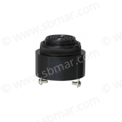
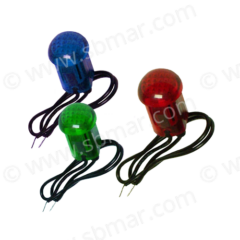
The buzzer and lamp can be single stand alone units with all of the switches wired to trigger the same piezo buzzer and lamp. This allows 100% flexibility as to changing the system over time and only requires a single home-run to the buzzer/lamp since you can daisy chain (parallel wire) the switches. When any one of the switches close (grounds out) the buzzer/lamp will activate. On the downside, this does not allow instant knowledge of what switch has been activated if there is no labeled lamp dedicated to each switch. Another downside is that a normally closed switch activates the alarm at key on which is a nice test of the circuit. If they are all wired to the same buzzer/lamp as long as any one switch is closed the alarm will activate at key on even if one or more of the normally closed switches in the circuit are not functioning.
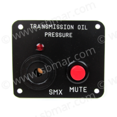
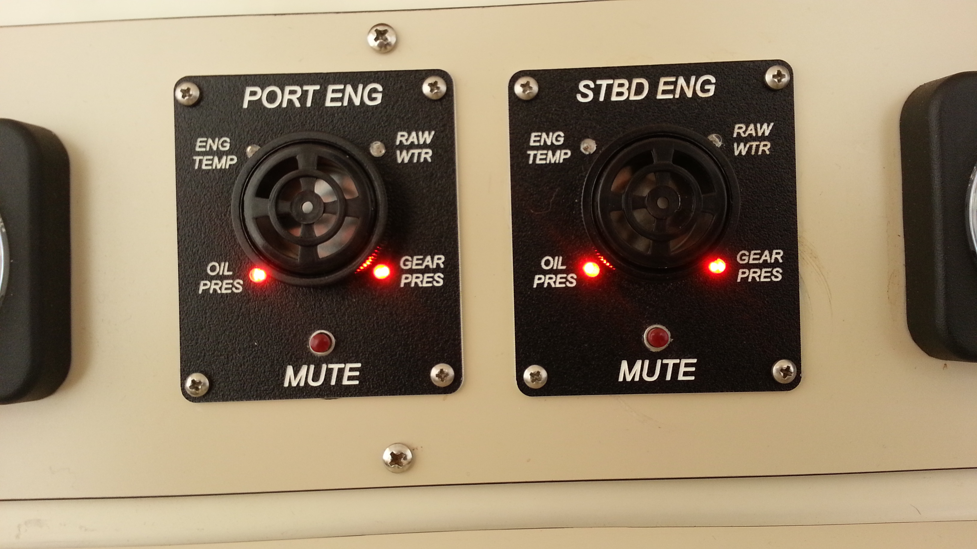
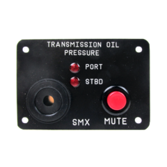
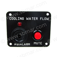
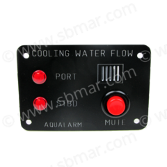
Another more sophisticated option is to have a panel with a single buzzer but a light for each switch being monitored in which case you will get the alarm sounding and the light will be lit immediately letting the operator know which switch/component has closed.
Having at least one normally closed (pressure monitoring) switch on your panel will allow the alarm to activate at key on thus confirming it is getting 12 volts.
Custom Alarm Panels
Wiring
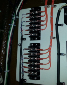
The wiring is an important step in keeping your system neat and serviceable.
Avoid homeruns from the engine switches all the way to the panel. Consider a terminal strip behind the dash and another strip in the engine room. Your feeds between the terminal strips can essentially become part of the boat. And then your wiring to the terminal strip at the dash from the alarm panels and your wiring from the engine(s) to the engine room terminal strip are kept simple and easily altered over time if the need be. Yes the terminal strips add more connections in the system but high quality terminal strips and high quality properly installed heat-shrink crimp connectors are trouble free.
The terminal strips also make for easy access test points when testing or troubleshooting the system.
The wiring between the terminal strip behind the dash and the terminal strip in the engine room should be a multi conductor 20-22ga stranded tinned copper. I purchased the multi conductor cabling from Orion Wire Co. in NH.
18ga wiring works well both between the terminal strips and the alarm panels as well as between the terminal strips and engine room switches.
You can label all of the wires but a simple and neater option is to just have a legend at each terminal strip so you have a diagram of what system each terminal is connected to. This is still on my “to-do” list but since no one other than me will have their hands here it’s not high priority.
Alarming High Coolant Temperature
Coolant temperature is probably the most important, and difficult, system to monitor on the Cummins marine engines. This alarm is important because the factory system van be too little too late in the event of an overheat as theses high output engines have no extra iron to absorb the overheat. If the coolant is boiled out the “B” especially will get localized hot spots which can damage gaskets, crack the exhaust manifold, etc. etc.
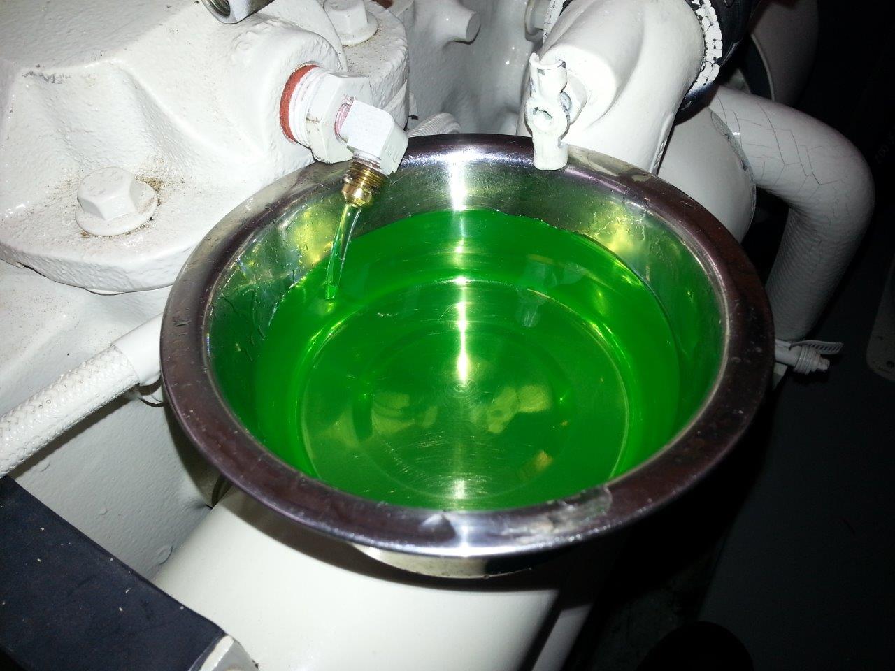
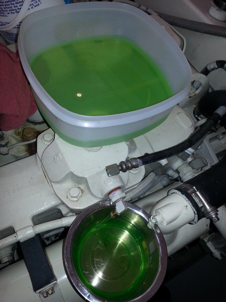
These are two coolant issues at hand – Is the coolant heating up or is there a coolant loss?
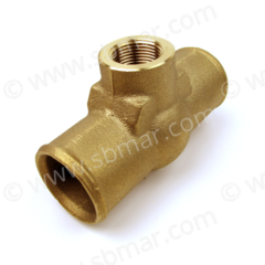
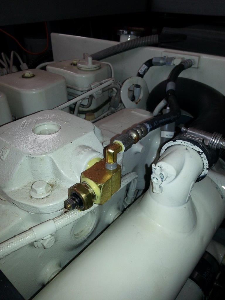
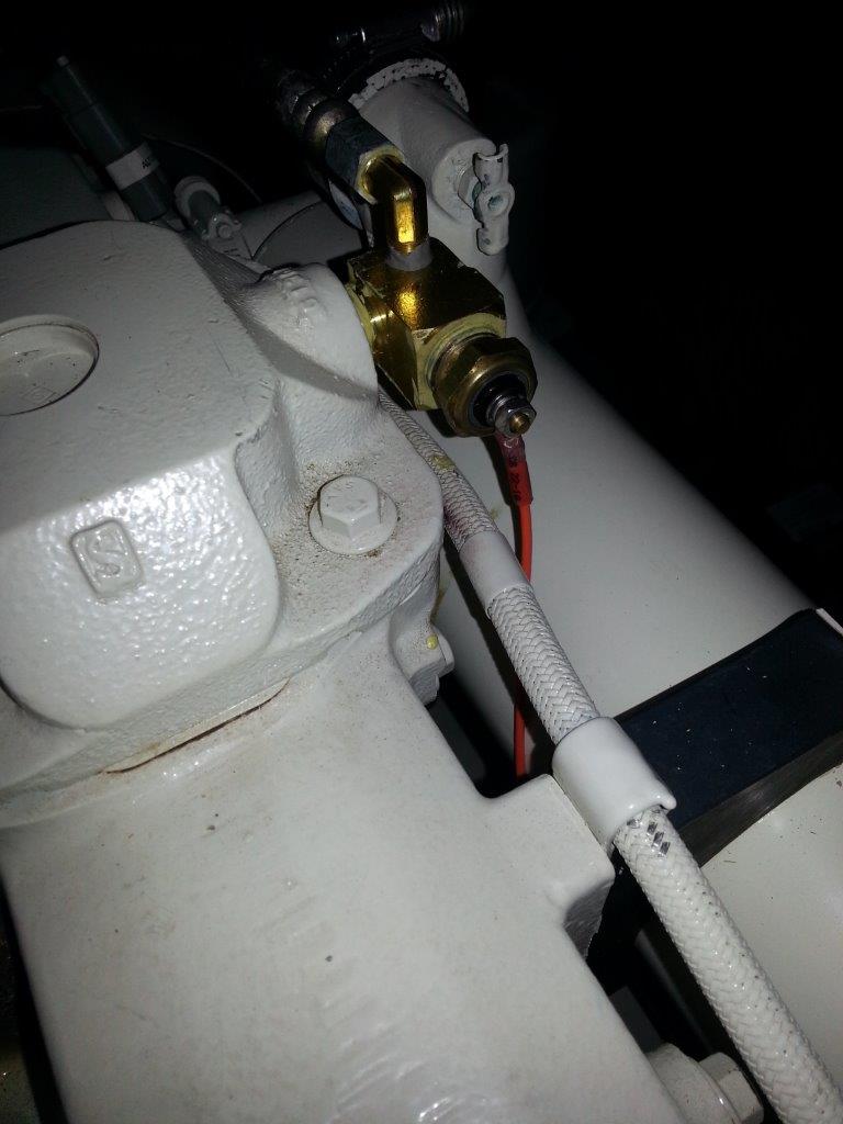
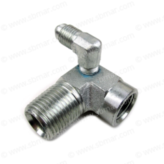
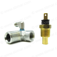
I have read contradicting feedback about a coolant temperature switch being less effective in the event of a loss of coolant. The coolant temp. switch in an adapter at the top of the manifold is a good location since it will get hot quickly as the hottest coolant will flow through it back to the tank. But is also very high in the system. Coolant loss would create steam here which should still trigger the switch. A second coolant switch lower in the system could be installed in the head which would be submerged longer. The manifold cap adapter and temperature switch can be sourced here.
The other issue with the common 205 deg F coolant temperature switch is that it’s set point is on the cusp of an overheat and you may be already be in the damage zone if there is any delay in it closing and triggering the alarm. There is very little available response time, especially when running up over 2,200 RPMs or so and boiling coolant happens fast. Therefore, we sometimes recommend a 165 deg F thermostat for those of us that run on plane which should keep the engine below 175 deg and then you can go with a coolant temperature switch lower than the 205 deg F. Custom made coolant temperature switches in the 190-195 deg F range are also available.
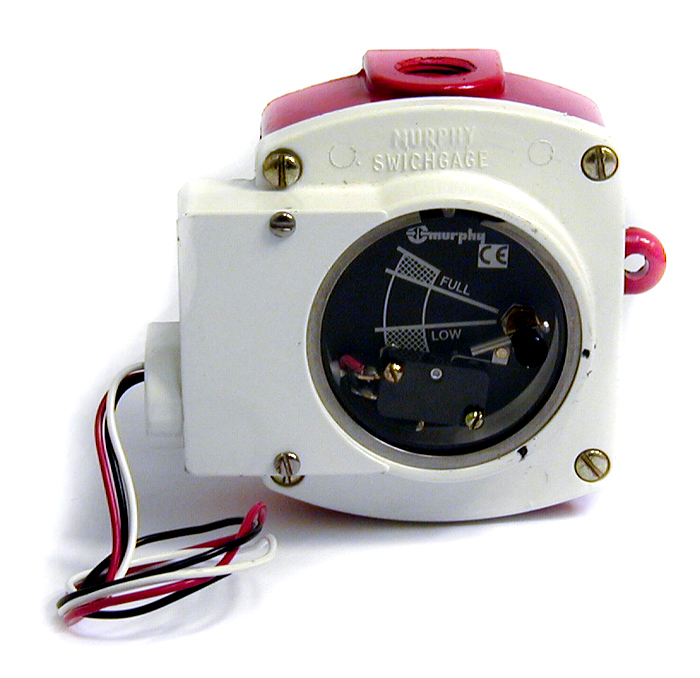
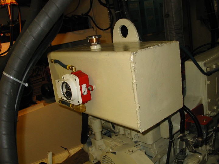
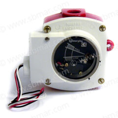
Detection of loss of coolant can be directly monitored with a Murphy level switch (normally open) mounted on the coolant reservoir/expansion tank. The Murphy gauge switch will close to sound an alarm when the level drops below a set level. The gauge also gives a reading of current level.
Alarming Low Engine Oil Pressure
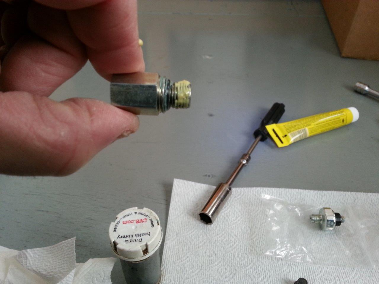
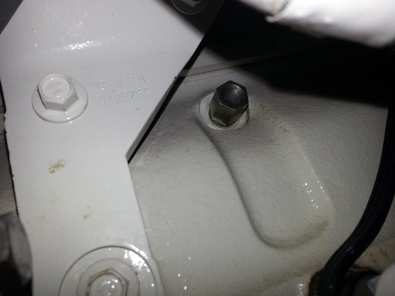
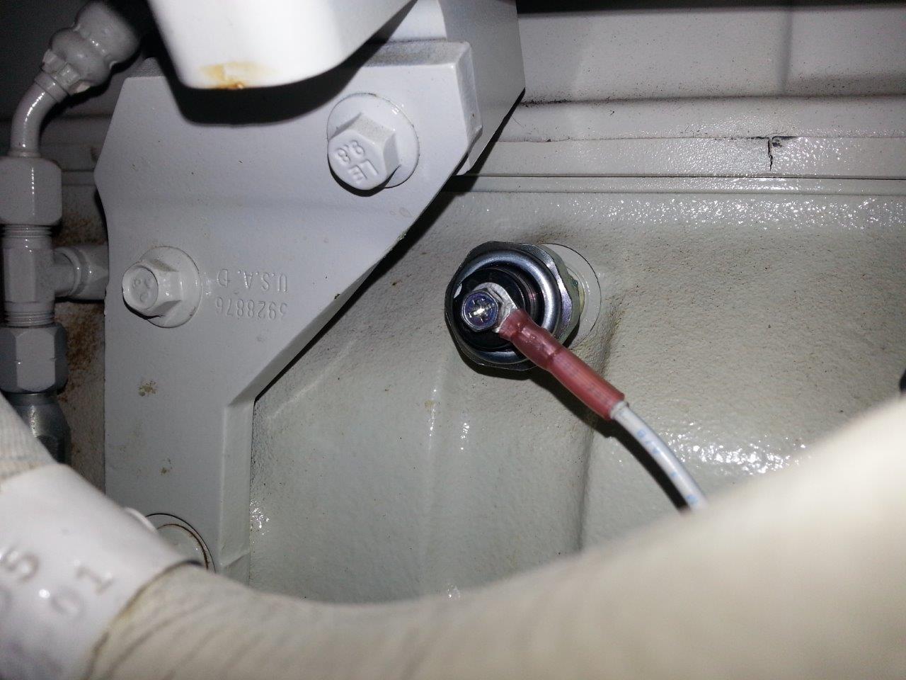
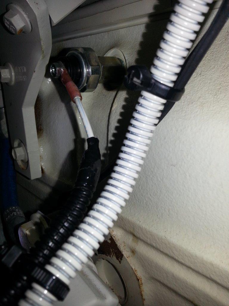
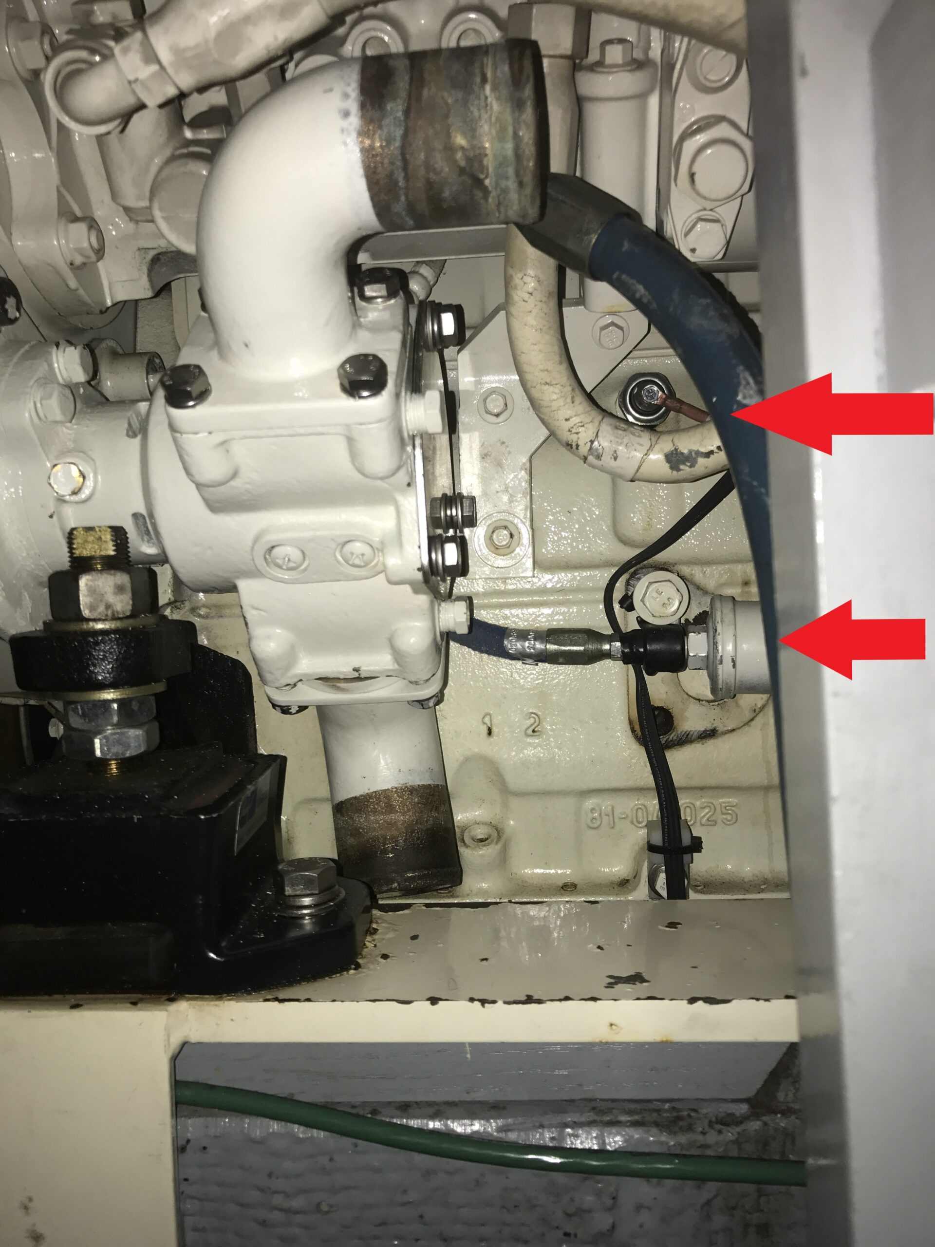
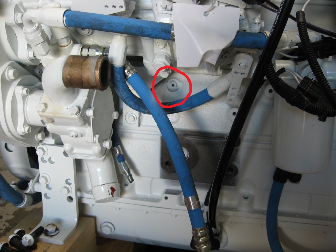
A normally closed 5-10 PSI oil pressure switch installed in the main oil galley is a simple install. However, when installing some find that the switch body hits the block casting because the port is recessed. Use 1/8″ metric fittings to bring the switch body out and away from the casting for proper install. The low engine oil pressure switches are usually a case ground switch which means that only a single wire will be required for the circuit.
Alarming Loss of Raw Water
Raw water can be measured in flow or can also be measured as temperature at the wet exhaust outlet.
Alarming the loss of raw water with a flow switch
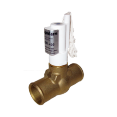
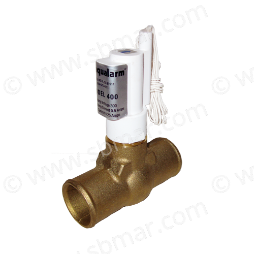
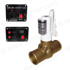
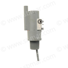
A flow switch is normally closed (NC) and opens when flow is detected. A raw water flow detector switch is an excellent choice for getting the earliest detection of raw water loss. However, there is a chance of fouling and issues due to normal sea water crud so they are not always something that is installed and forgotten about it which is par for the course with anything that is in contact with sea water. At the end of the day it is a superior choice on the raw water side of the engine to alarm against failures such as impeller failure, seawater circuit clogging, hose failure, etc.
Alarming the loss of raw water at the wet exhaust outlet
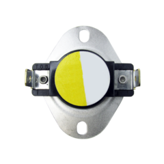
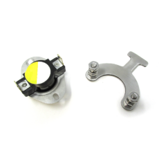
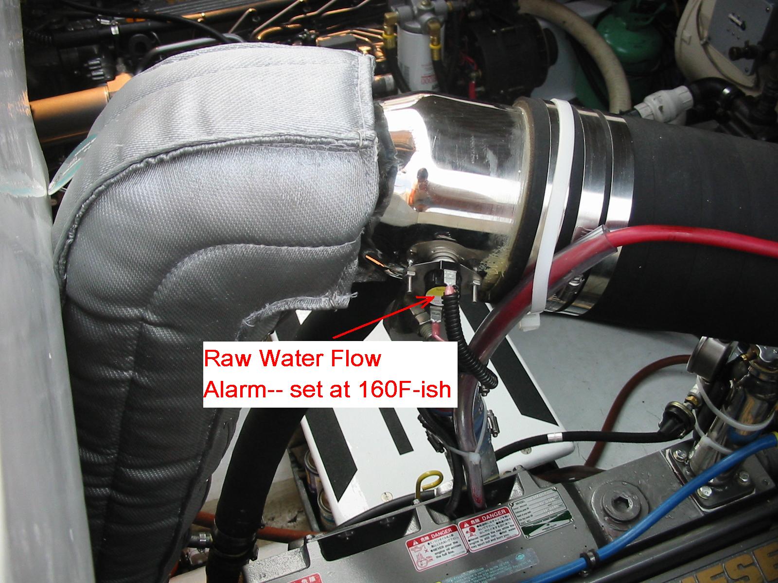
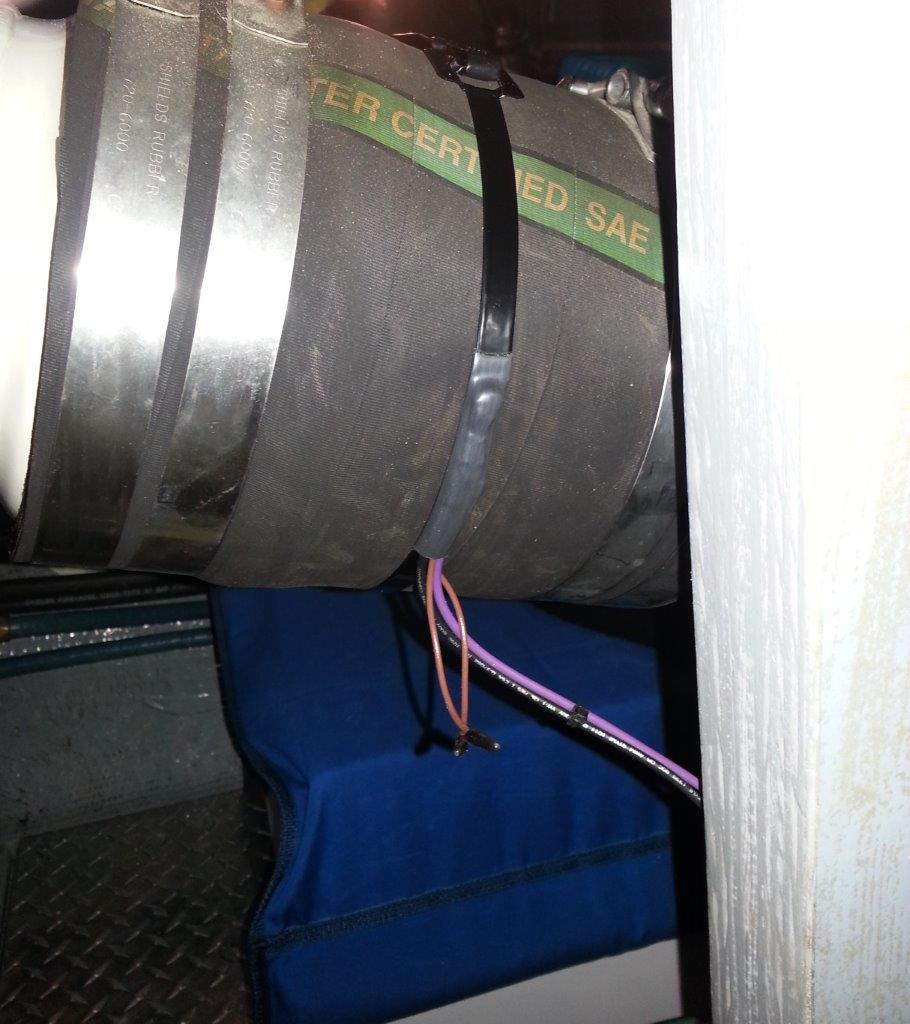
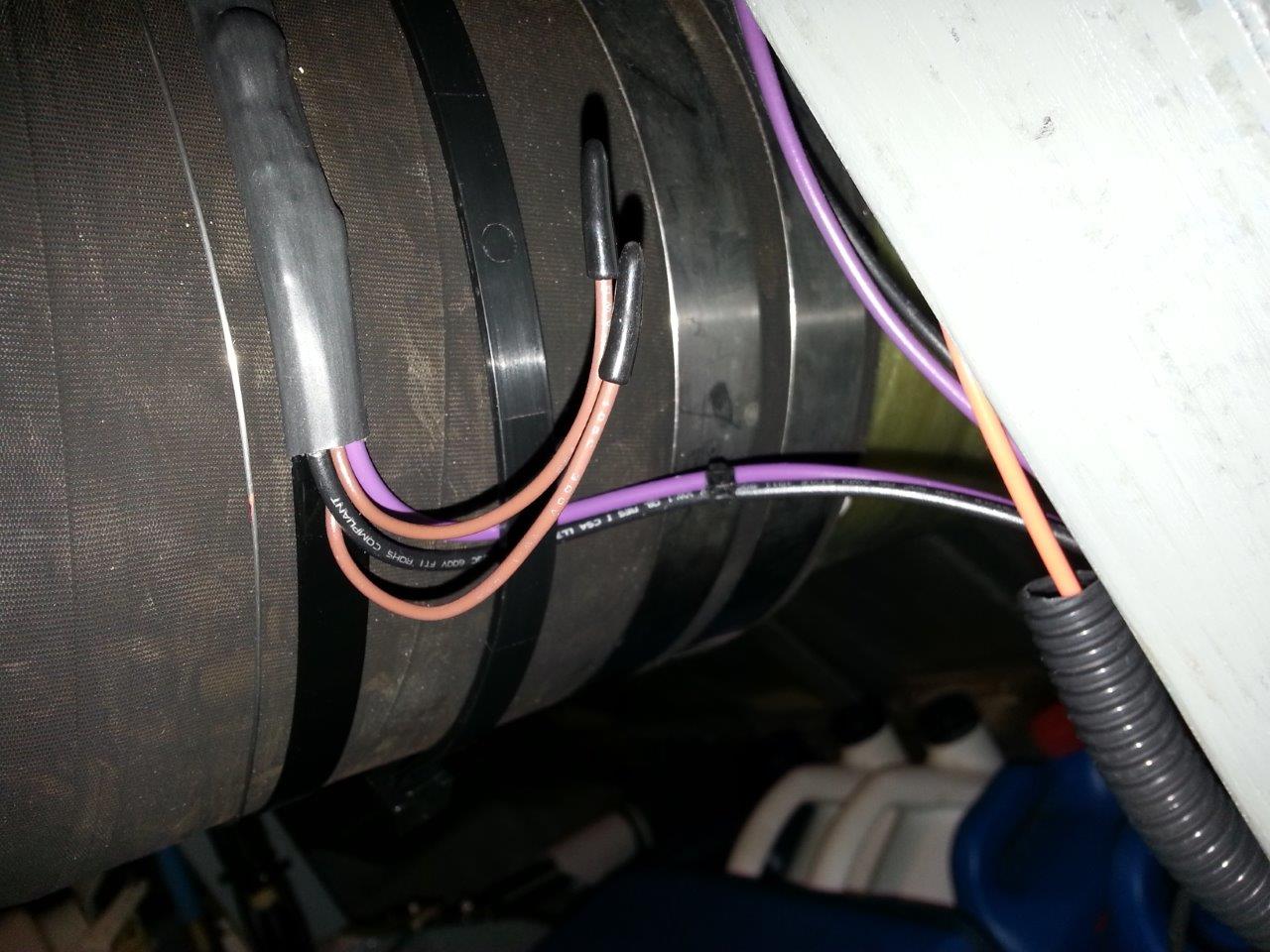
Another method of monitoring raw water flow monitor exhaust temperature so there is no actual water contact. An available option is a wet exhaust temperature alarm switch on the shower head with a set point of 165 to 180 deg F. This can be fitted to a custom riser/mixer. If you’re running factory mixers a simple solution is the Borel Mfg. temperature sensing band that goes on the exhaust hose immediately downstream of the stainless hose clamps at the mixer. These bands contain a normally open (N.O.) thermal switch with a set point of 167 deg F.
Since a flow switch is N.C. you will have a system check with key on. The bands are N.O. so no such check at key on. The bands have sensor wires (under protective caps) that you short together for testing purposes.
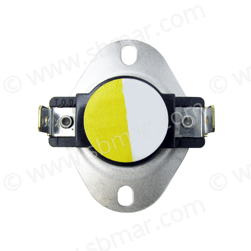
Another exhaust mixer option is to use a thermal switch that can be “tacked” to the mixing elbow that will also detect raw water temperature above 180 F.
Alarming Low Gear Oil Pressure or High Gear Oil Temperature
Gear monitoring can be via temperature or pressure. A noted gradual increase in temperature could be an indicator of bearing failure. Or an increase in temperature could be triggered by slipping clutch plates that are heating up at higher output. However, monitoring pressure is more common with the recreational boater and can be an instantaneous indicator of loss of lube as in a gear oil cooler failure.
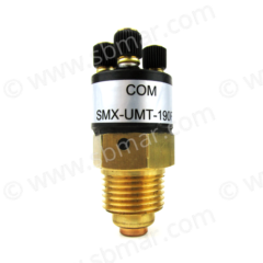
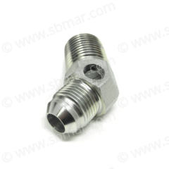
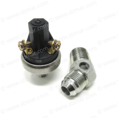
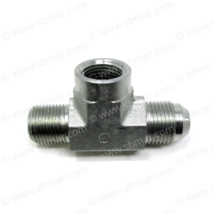
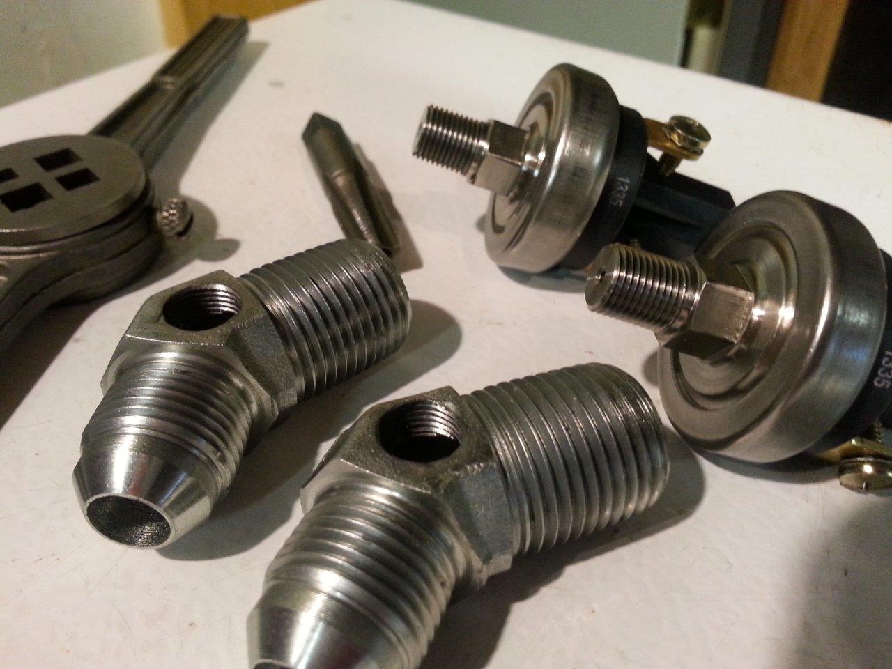
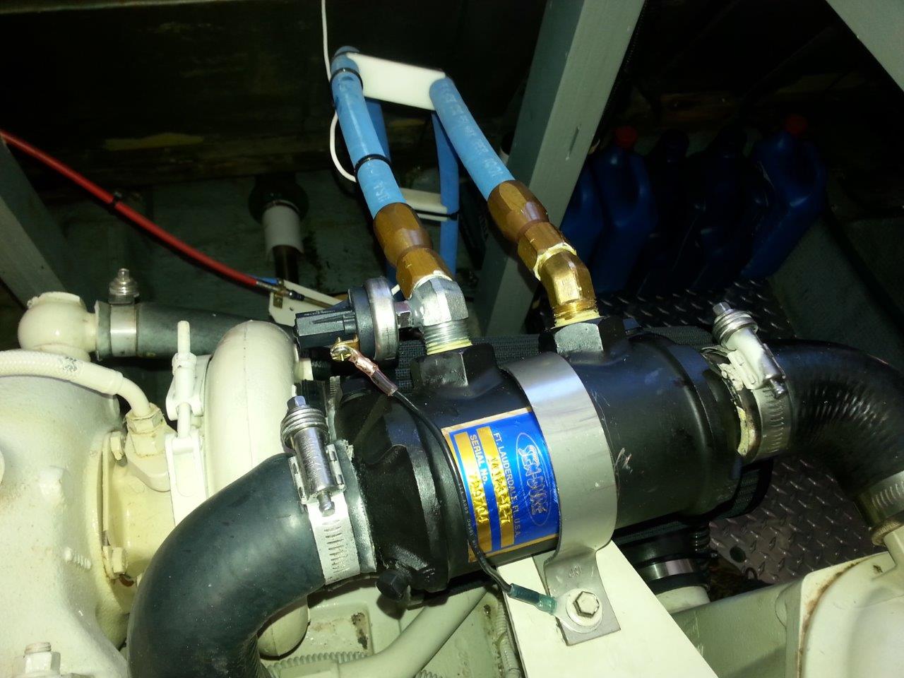
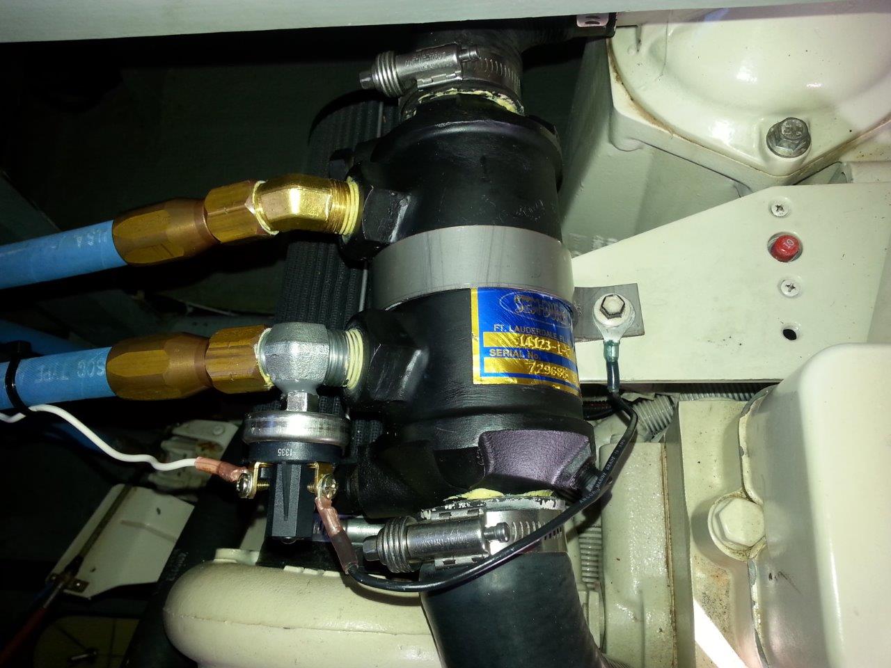
A steel (not brass) gear fitting at the cooler can be drilled and tapped to accept a pressure switch. As the gear pressure can be in the 400 PSI range one has to be mindful here.
The switches are adjustable so you can lower the set point to the point where you don’t get the “chirp” when shifting or do as I do and leave the chirp as it’s good piece of mind that all is working as it should.
Alarm Systems & Switch Products
