Designing a marine exhaust system for a boat is something that apparently takes the back seat during the planning stages when doing a repower. In new boat construction, the design of many systems seems to center around the “cookie cutter” philosophy, as builders always seem to want to or work around a factory designed wet elbow system that is supposed to “fit all”. Besides that, many new builders are more concerned about getting the engine below a low deck than worrying about the exhaust and exhaust outlet of the engine being close, at, or BELOW the water line.
Also, and another all too common error in exhaust design, is the use of an anti-siphon valve as a “fix-all” for an otherwise poor and sure to fail design. It’s not that an anti-siphon valve is not needed in many applications, but “Average Joe” has no clue as to what they can do and more important, what they CANNOT do, and how small changes in the basic design of an anti-siphon valve can greatly enhance its effectiveness. More on “Anti-Siphon” valves and their shortcomings below.
The most BASIC of all supposedly understood but not followed diagrams of a marine exhaust layout is below. Why is it we continually see the LWL of a vessel within just a few inches of the exhaust spill-over point? Notice the word MINIMUM??
REMEMBER this as the “SPILL-OVER” point
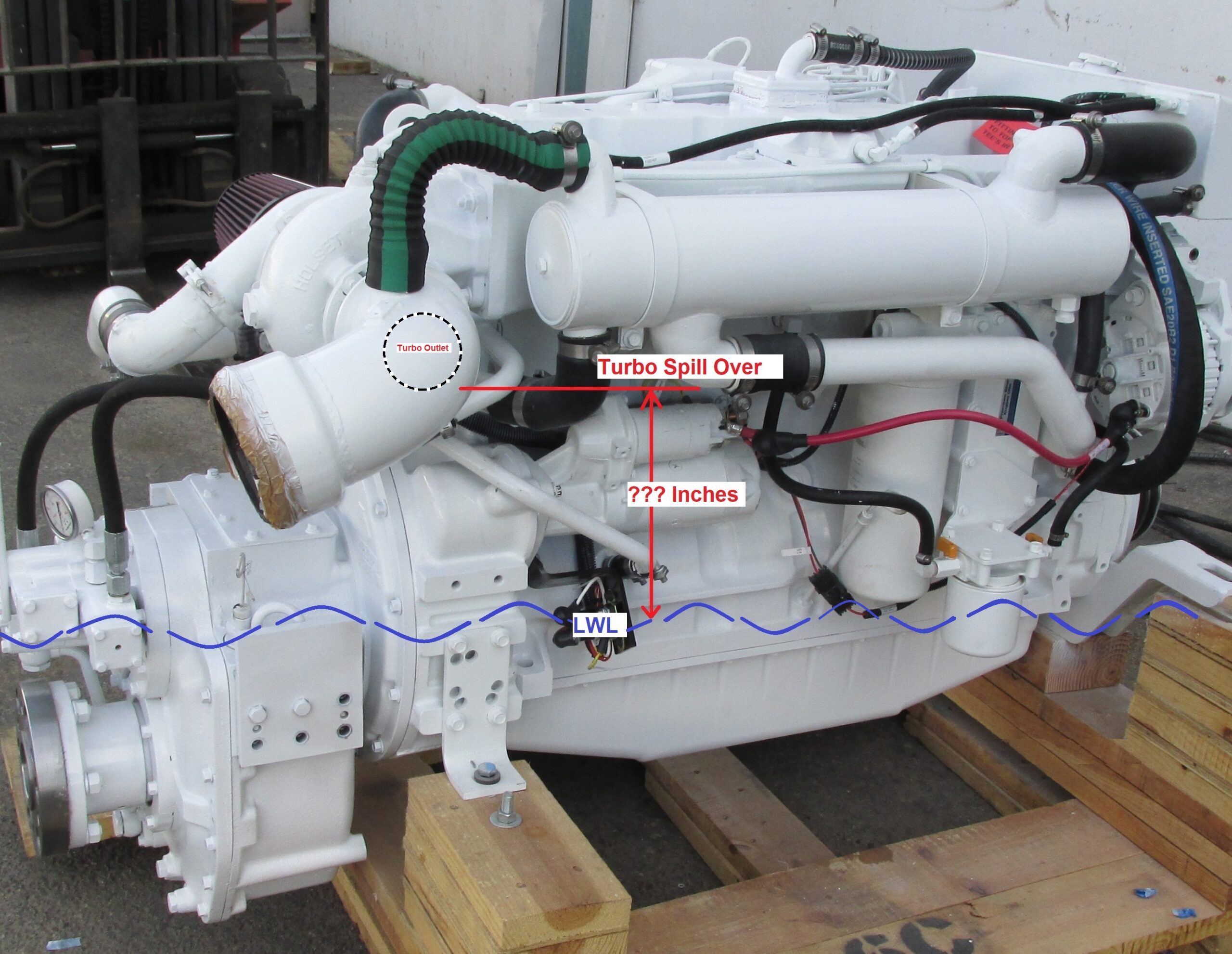
The diagram above seems to elude new boat designers and “repower experts” in so many designs that have cost vessel owners millions of dollars over the years in ruined engines. Simply unbelievable to me that something as simple as building an exhaust with a minimum of 12″ of safety margin height is not followed.
Moving on to the total design of the system is where most of the emphasis needs to be when repowering or building a boat. With “design” we mean the entire system from the engine exit point (the turbo outlet in most cases) all the way to where the exhaust leaves the boat. This includes the “size(s)” (just figured that one out), from the engine to the final exit, type of muffler, if any, type of material for both the dry and wet side of the system, and the general routing and actual installation of the system. It seems that many installers and builders plan this very important part of the vessel as an “afterthought” because many great engine rooms are built with no room remaining to build a safe and well planned exhaust system.
Material choices when building exhaust systems can vary, but 25+ years of experience and 100’s of exhaust systems under our belt in high hour commercial applications have shown us that 304L or 316L is good for all of the dry sections and shows no difference in lasting ability regardless of what “street talk” says. Using 316L for all wet sections is always best. Use 316L rod for all welding (304 or 316) and if the design uses any mild steel for the dry section, then use 309L for the mixed joints / weld area. TIG is the method of choice for all welding. For all custom FRP exhaust work, the of use resins that are Class 1 fire retardant isophthalic polyester resins are our choice and easy to source. Common industry names are Reichhold (DION) and McNichols and are used extensively thru the FRP structural pultrusion process and filament winding manufacturing industry. You may also find many of the more common iso-tooling resins meet these specs and are also an excellent choice to use, although some do not have the Class 1 rating. IMO, 99% of the time, Class 1 resins are not needed unless the spec calls for it.
Resin rich lay-ups are best with plenty of thickness ( ¼” to ½”) in all joints building up with glass-strand mat with a layer or two stitched fabric in-between. We finish with iso-gel coat and surfacing agent when applicable / paint as to what looks right for the job – in all cases our work is always vastly more stout than “factory supplied” FRP parts, and we always put a 2″ – 4″ long tube doubler inside all tubes where the hose clamps go. This eliminates the tube crushing that factory pipes/ muffler spigots seem to be very susceptible to.
With sizing and basic construction covered, let’s get into exhaust design, as this is the most abused and least understood phase of the overall system. “Gravity,” I’ll say it again, “G-R-A-V-I-T-Y,” is the most important aspect of the design that needs to be addressed and how you can use that force to help you design a safe and effective exhaust system. Next is understanding and knowing where your waterline is in both static and all running conditions.
With those ideas fresh in your mind these are some pointers and concepts that you need to consider in the initial planning stages of the design layout:
1) Understand the difference between a “requirement” and a “recommendation”
From the engine manufacturer regarding exhaust design. They may “require” a minimum specified exhaust height for safety, but “recommend” a particular size for the system based on past experience. Many times smaller exhaust sizes can be used to everyone’s advantage and employing an experienced company w/ hands-on experience for this part of the vessel construction or repower is time and $$ well spent.
2) Always use gravity to your advantage
Water flows downhill so, if you have a system that holds water (water jacketed risers for instance) and this system fails internally (it’s not IF it is going to fail, it’s WHEN it will fail), where will the water go?? Into the turbo/exhaust manifold/cylinders?? Think about YOUR riser or elbow should it fail internally where you can not see it and what might happen. Remember, WET risers are an absolute no-no for any long term application unless they are “coolant cooled.” Internal failure of “wet elbows” and custom water jacketed risers is an old and ongoing problem, regardless of material choice and/or other claimed construction features. (See Tip #7).
3) Always use all of the available height in the engine room
For the riser (where needed and is practical) BEFORE turning over the top and injecting water; i.e. always inject the water on the downhill side, or down stream of the top of the riser. A wet exhaust system with a steep downward slope is always better and safer. The cheap way out, by using a factory supplied “cookie cutter” designed wet elbow, is not always a good or safe option. When thinking marine exhaust, remember “one size” DOES NOT FIT ALL.
4) Be sure that IF the option presents itself in the design of a wet exhaust system, allow for all of the water to drain itself from the exhaust when not running
Although this can’t always be done, you can still build a safe system by utilizing other simple design ideas, custom mufflers, surge tubes, etc. An important point to remember, IF your muffler, etc., holds water in the static position, then the system is also holding water when lifting/pulling the boat at the yard. ALWAYS lift the bow first (noticeably bow high) and hold it there for a minute or so to let the water drain from the system. I have seen quite a few destroyed engines that had water slosh up into the cylinders from this exact scenario of water rolling back and forth or lifting the stern first when pulling a boat – Usually this is not discovered until launch time and by then the engine is toast.
5) When using a “lift muffler” design, remember that in most cases you can make the system “inherently safe”
By being sure that the engine “spill-over” height is higher than the lift muffler spill over point. When the water injection is below the water line, you can also design an “active” anti-siphon valve that is much safer than the typical “auto-type valve” shown or used in most applications (IMO, they are a poor design and should be avoided unless fully understood as to their shortcomings and checked for proper operation on a continuous basis ).
Some of the fallacies that still persist today are shown in the “copied” lift-muffler design below that is shown in current high dollar color catalogs touting their exhaust muffler products. Thinking that this is an applicable base type design for a lift muffler system is 100% hogwash and in many cases leads to ruining a perfectly good engine because of water rising within the system before the engine starts and after it is shut down. What they should be saying is to design a riser BEFORE the water injection to use all of the height available within the engine room, and to design an anti-siphon system that allows an active and “open” siphon break to be on the upward rise of the water injection system allowing water to flow over the side BEFORE the water flows into the lift muffler filling the system.
Again, another instance of 100% “couch engineering” from an engineer that has probably never done and/or seen an install of a marine engine at or below the waterline and only gives or sells his “expertise” based on theoretical circumstances on paper calculations. This kind of literature angers me as I know it’s total garbage. However, I do admit that when this type of engineering is taken for “gospel,” I make lots of $$ because it assures me of continuous new engines sales down the road.
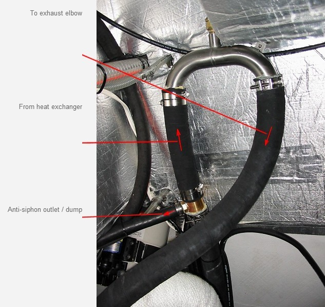
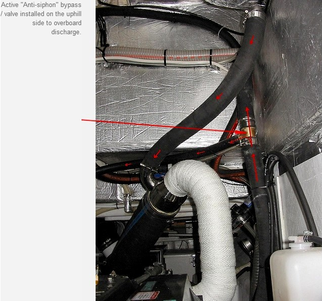
The general layout of the “anti-siphon” valve. In reality, it’s not a valve at all, but an active bypass that should be installed on the uphill water flow before it goes over the top, and discharged over the side above the waterline in a VISIBLE location. This allows cranking without flooding the lift muffler and adds an enormous layer of safety to the system.
6) Overall Exhaust design can usually be made better in many ways if you DO NOT use “cookie cutter” type exhaust components
Typically, many use factory 90 degree wet elbows, and an array of 45 and 90 degree bend hoses and clamps routing an exhaust. I guess most installers think of a marine exhaust system like copper plumbing in a house.
A simple change from a 90 degree angle bend to a 75 degree bend, an angled input to a muffler, or an added twist in a riser can make a world of difference in overall exhaust layout. In other words, don’t just think “straight, 45 & 90” when designing an exhaust system. In the 100’s of exhaust systems we have designed over the last 25+ years, I am sure that at least 50% of them had to have something custom done to a “factory muffler” in order to make the exhaust layout “fit” design criteria.
An Interesting Note: I have tested the pressure drop of a typical 75 degree custom elbow from both 6″ to 8″ and 5″ to 6″. In both cases, at 430 HP on the 5-6″ elbow, and at 660Hp on a 6″ to 8″ elbow, I never saw more than ¼” Hg delta. Going from smaller to larger allows a quick expansion and lowers pressure restriction overall even in relatively sharp wet bends. Less bend would even be better.
7) Never, never, never do you want a boat that has saltwater cooled wet risers or pipes unless they are installed in such a manner that when they leak they are downhill of the engine “spill-over” point
It is not IF they are going to leak, it’s when they are going to leak as it is a 100% given that they will. If this is the only viable option, then be sure that you realize that they need to be inspected annually (or more often), or changed out after every few years to be safe. A few examples below of perfectly good low hour engines that had a “wet riser” or something similar and when they failed internally, the owner was into the BIG bucks as to repair.
8) When the vessel design is such you are very limited as to the physical dimensions of the exhaust size
(like installing a muffler in a confined space) and you need to reduce back pressure but you cannot install larger pipes, tubes, etc, another option would be to bypass some of the water that is normally mixed into the wet exhaust.
In most cases, the engine seawater system pumps more than enough water to cool the engine and sometimes as much as 2+ times water than needed to cool the exhaust.
This can vary as to engine design AND exhaust design, but bypassing approx 1/3 of the water that leaves the heat-exchanger or cooling system on the engine and sending it over the side of the boat can easily reduce back pressure by 1″ Hg or more in some cases.
An added benefit of this is that it can add a “visual” as to water flow and, in many boats, this would be a plus as the seawater water flow is sometimes impossible to determine.
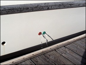
Knowing that you are pumping seawater always adds comfort to your experience. If this is something that you feel would be needed, use the services of a company that has a track record in this type of work as it would be time and effort well spent.
9) Reference sketches and ideas:
Marine exhaust system design failures
[hr style="line" size="1px"]1) New 44 FT power Cat from Australia with new 6LYA Yanmars
The boat was sold here locally and on the first trip out to the islands in “prevailing weather,” while fishing with the engine off and the boat bobbing up and down, both engines had the aft cylinders fill with salt water. Luckily the captain called me and I told him what he had to do to salvage the engines. That night after a long tow back to the dock, we pulled the injectors and flushed the cylinders out. The next month was spent re-doing the exhaust system (about a $12K job).
2) New 26 FT vessel with a Yanmar 6LPA and a Bravo #3 drive.
The stock riser was about 2″ above flooding when brand new and within the first year, as the vessel got loaded with “gingerbread,” the engine flooded at the dock. The engine was toast and the owner had to buy a complete NEW engine.
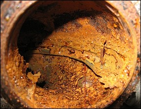
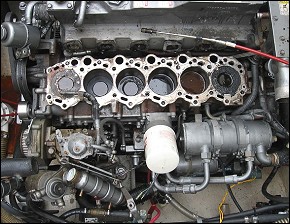
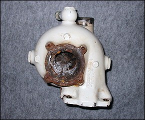
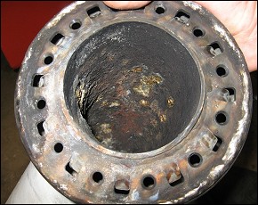
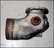
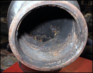
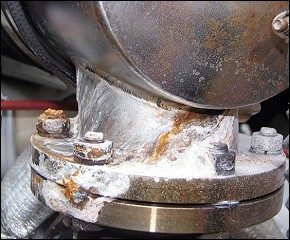
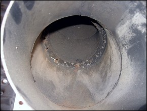
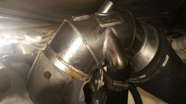
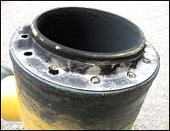
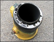
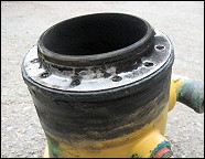
3) 3126 CAT Factory Wet Risers & result
These pictures show what is “typical” marine type couch engineering mixed with FACTORY salt water cooled wet risers that were installed on a 3126 CAT. The factory risers were made of Stainless Steel with the salt water inlet at the bottom of the riser. Two things happened over 4 years and 190 hours. Because the riser outlet at the top were designed and installed at such a “shallow down angle” (have seen this on new Mainships too), water would drip down the riser during cranking and after shut down damaging the turbo. After about 3 1/2 years/200 hours in service, the riser failed internally leading to total failure of the turbo and failure of the #6 cylinder exhaust valve. CAT later changed from Stainless Steel to Bronze construction for this design (that solved the “rotting out internally part” of this poor design) only to have the shallow angle of the outlet come back and bite them on many Mainship installs. It took CAT engineers about 7-8 years to understand the issue (gravity being the main culprit) and they finally dumped the entire design with the last generation of 3126 CAT’s and the newer C-7’s.
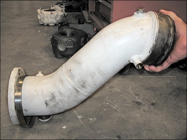
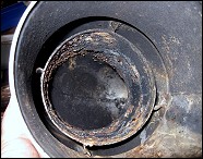
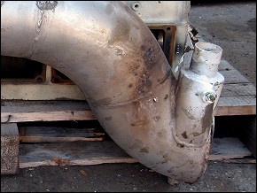
4) Factory wet elbow made from junk materials
If you recognize this design of a wet elbow on your boats exhaust system, I’d be checking the internal condition of it often after the first 3 or 4 years of “marine age”, regardless of total engine hours….
5) Results of a very poor design from a “builder” that wanted “NO INPUT” during the construction
Original builders design and installation: Results of very poor design and “Mickey Mouse” exhaust wraps. On the maiden voyage and seatrial, engine room ceiling tile caught on fire.
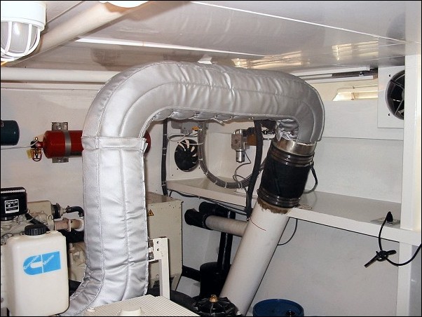
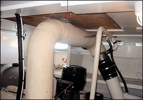
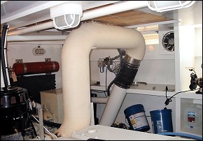
Our Solution: A re-designed riser and mixer, proper clearances and supports, and 1st Class Exhaust Insulation on the dry sections. In the big scheme of things, this could have been an expensive learning curve. Guess who’s wallet picked up the $6500 “redo” tab? Just like most of the time, the owner !!
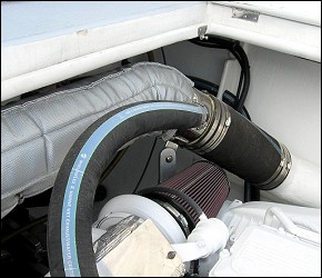
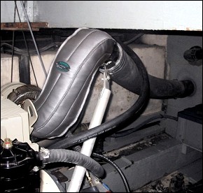
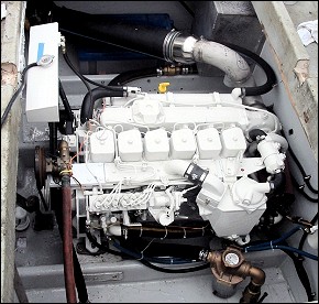
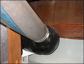
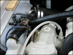
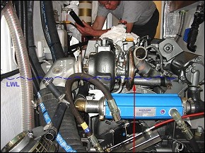
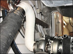
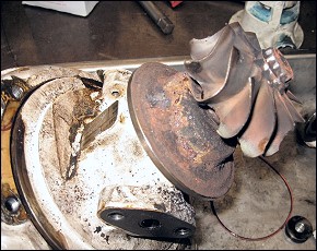
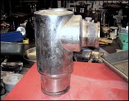
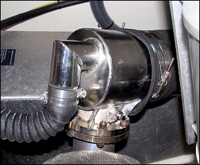
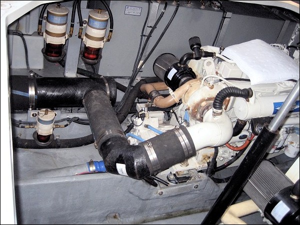
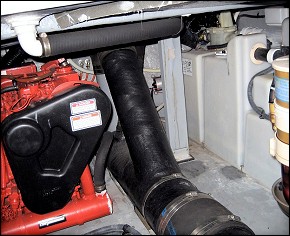
6) Volvo Factory supplied wet mixer for a newer Volvo TAMD 120
This is a Volvo Factory supplied wet mixer for a newer Volvo TAMD 120. At 800 hours and 4 years the owner was complaining about black smoke. We pulled the air cleaner and found the turbo was binding.. Noticed external water leaks on the factory supplied exhaust mixer and pulled it. The inside was also leaking and some rust was apparent on the exhaust turbine wheel w/ lots of crusty carbon/salt build up.. Cleaned it all up and installed a new “factory elbow” at the tune of $2800 each – he did not want a custom unit. The overall design, multiple pieces, and internal seams and welds says it all. Very poor design and he is sure to see the same failure again as the new elbow was of the same construction. In my opinion, the owner got off easy as it could have been a lot worse.
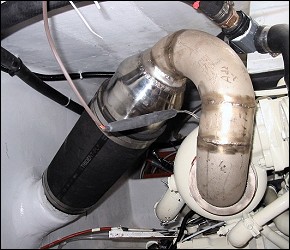
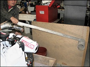
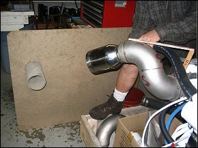
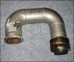
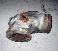
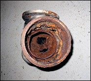
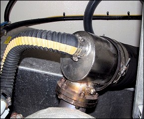
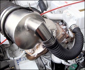
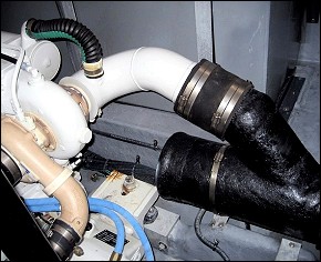
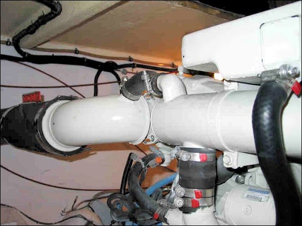
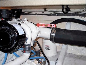
7) Lack of thought as to both raw water flow, dry riser design
These picture’s are a perfect example of a design that may impress a buyer but shows a total lack of thought as to both raw water flow, dry riser design, and long term reliability and safety for the engine because of the “jacketed design” and orientation. Not only does the raw water input elbow go against any common sense as to water flow restriction, with the overall design with internal welds in the jacketed area, this elbow will fail and leak into the turbo when it does rot out internally (just a few years down the road at best). The supplier (a well respected popular engine distributor) should not be in this part of the business, or at least use a different company to design and build the exhaust mixers and risers. The first pair of supplied units were recalled for possible cracked welds. Just another sad example of “couch engineering”.
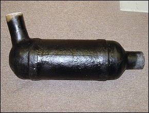
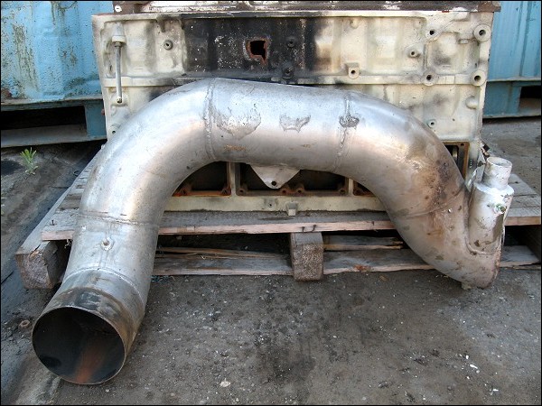
8) Complex SS wet riser that the owner thought was “cool”, but after 1 year of frustration and over $10,000 in repairs, he finally saw the light.
The designer/fabricator tried his best to make a buck – This riser was on a Detroit 650 HP 8V-92 and failed in two ways – The exhaust sprayer (inside pic) was clogging and the engine would either overheat or the raw water hose would burst – One time the burst hose took out a new Inverter. Then, after dealing with that issue (working with another local mechanic that had no clue) the unit failed internally and took out the turbo. About $10,000 later we finally got it fixed right. Moral of the story: Never never do you want a raw water jacketed riser!!!
9) This design went 3 months before the engine hydraulic-ed for the last time
This builder thought for sure you could put the riser/turbo at the waterline, inject water in a jacketed riser that is close to level, and then push it up hill – Within 3 months and less than 25 hours the engine had water in the turbo and cylinders – Actually it probably had water in it the first day, but somehow the engine did survive for a couple of months… What was he thinking!!!
10) “Doomed”
This is another example of a repower job that cost a extra few bucks after someone thought they had it right. The “repower guy” seemed to think that exhaust systems could be plumbled like water pipe in a house and attempted to use the factory “one size fits all” cookie cutter wet elbow. He also forgot about gravity and within 2 weeks had starting problems. The turbo was getting washed daily with salt water… Designing a proper riser the first time around is always cheaper.

11) Poorly designed wet mixers
These pictures depict what we see quite often with the CATAPILLAR factory wet elbows – Poorly designed wet mixers that “clog” unnecessarily due to a “couch engineered” design…With all the issues we have seen with the different type of CAT Factory wet risers and mixers, I really wonder where they hire their engineers from.
We are here to help, so if you need anything, just drop us a note or post on the forums.