 Like many vessel owners, you are not alone if you’re wary when the “V-word” is mentioned. This goes way back, because using a “V-drive” requires a lot more design and installation thought. The general configuration is not forgiving unless done right, but absolutely if done right, the V-Drive layout can offer good reliability compared to any in-line drive, along with offering many more advantages in some installations.
What most people fail to understand is that with any install, inline or V-drive, the shaft / gear box arrangement and it’s general location does not change, it is the engine that swaps position that makes the biggest difference in the design layout while also giving the this configuration its name “V-DRIVE”.
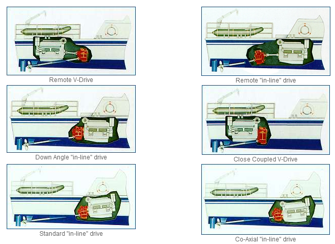
THE BASIC LAYOUT OF THE ENGINE IN RELATION TO THE TRANSMISSION IS EXPLAINED BELOW:
| 1) – Engine coupled to the transmission towards bow of boat – closed coupled in-line drive, down angle, drop parallel, or co-axial. |
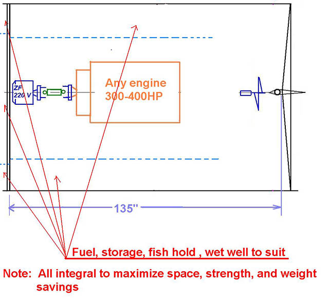
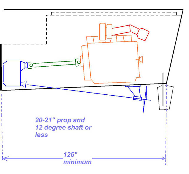
| 2) – Engine coupled to the tranny towards rear of boat (Closed Coupled V- Drive) – engine weight, not transmission weight, shifted aft approx 3-4 ft in smaller engine installs compared to the same boat with an in-line. |
| 3) – Engine removed from the transmission and moved towards rear of boat (Remote V- Drive) – engine weight, not transmission weight, shifted aft approx 4 ft-8 ft in smaller engine installs compared to the same boat w/ an in-line. This usually allows the best access to both components. |
Remember that in all cases regardless of which drive-line layout one uses, the shaft/struts/log and rudder components, are generally all the same.
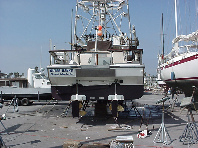
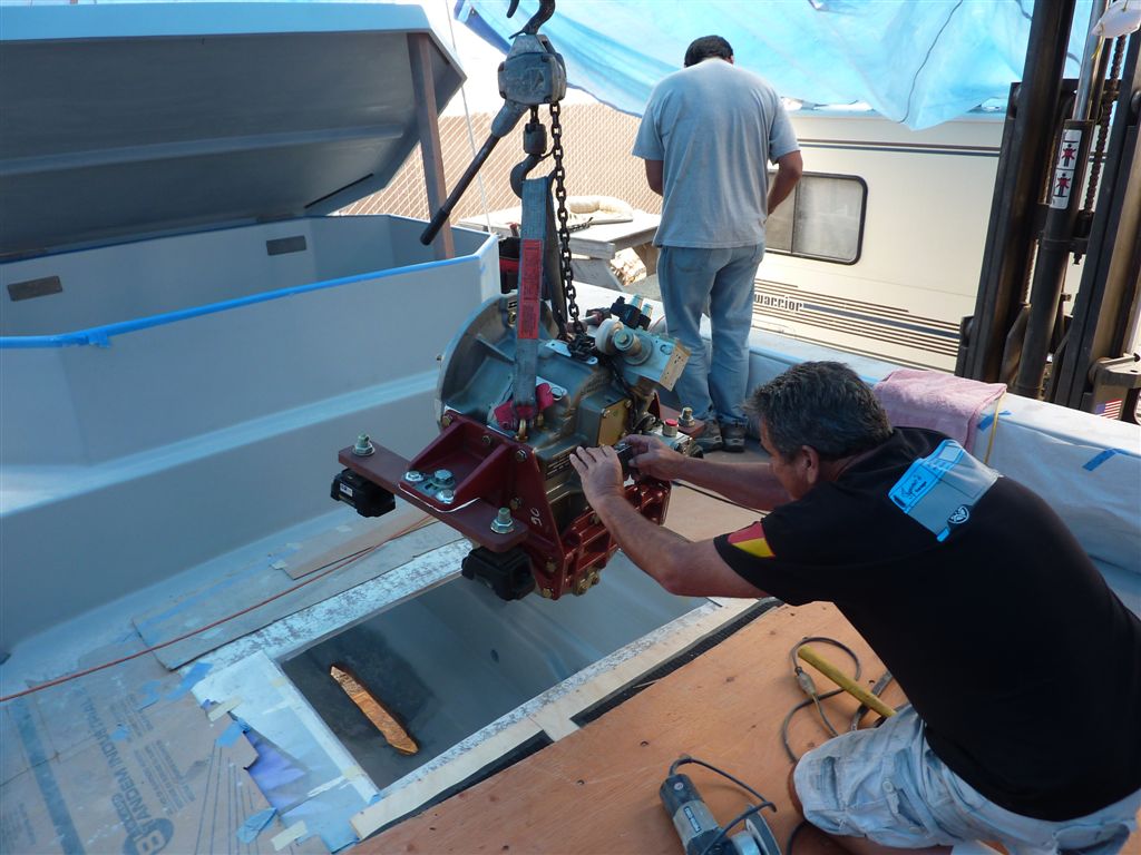
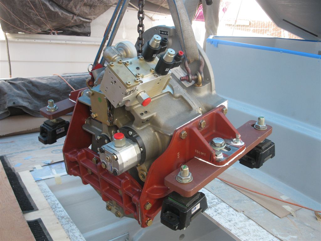
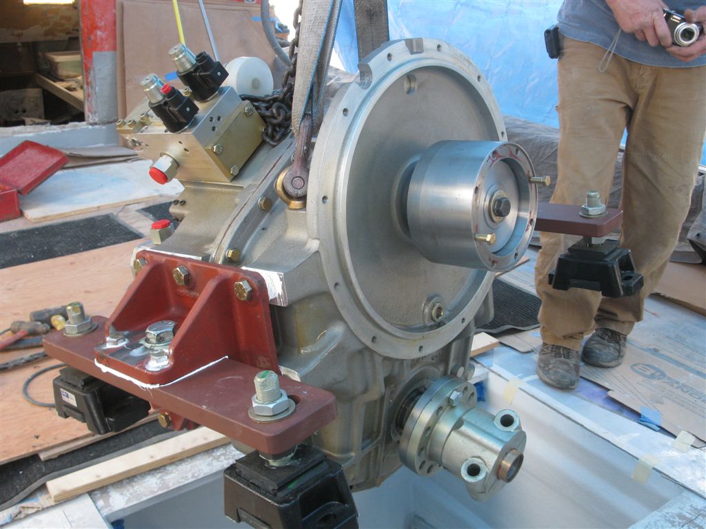
Seaboard Marine is one of the largest installer and supplier of V-Drive diesel powered commercial boats in this country. We consult on a regular basis w/ many small builders of custom boats and have done over 60 V-drive installs for both commercial and recreational vessels ourselves – Lots of experience, and I would say without any hesitation, the nicest and fastest boats we have repowered, designed, or built from scratch, are V-Drive powered. Many of our customers come to us specifically because of our vast experience w/ this type of engine/transmission configuration.
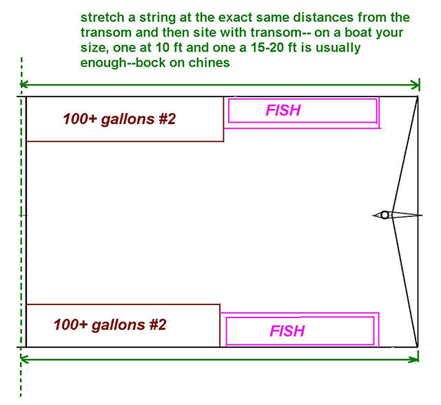
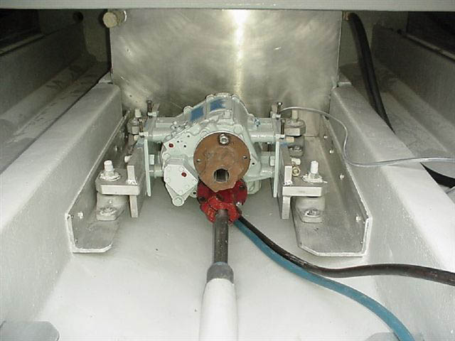
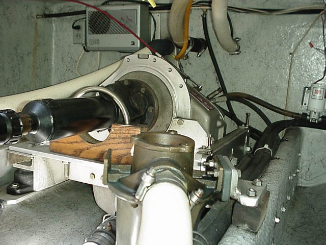
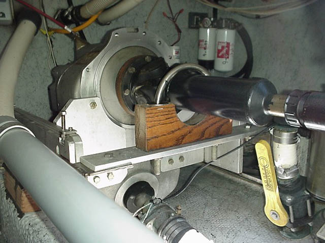
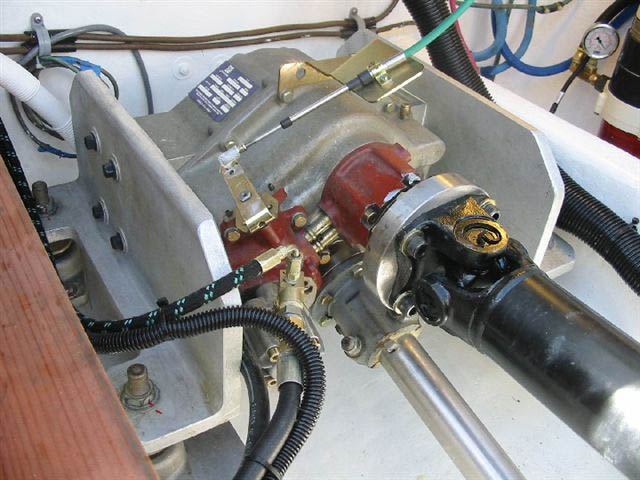
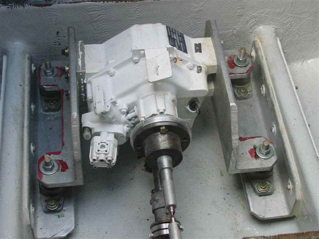
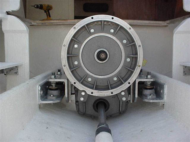
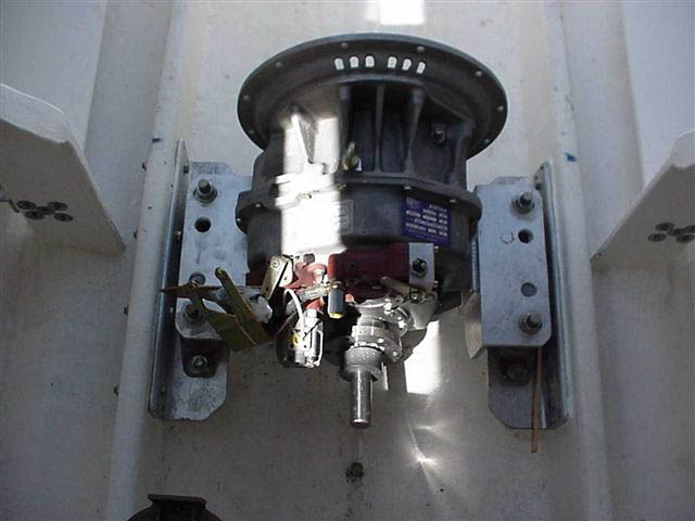
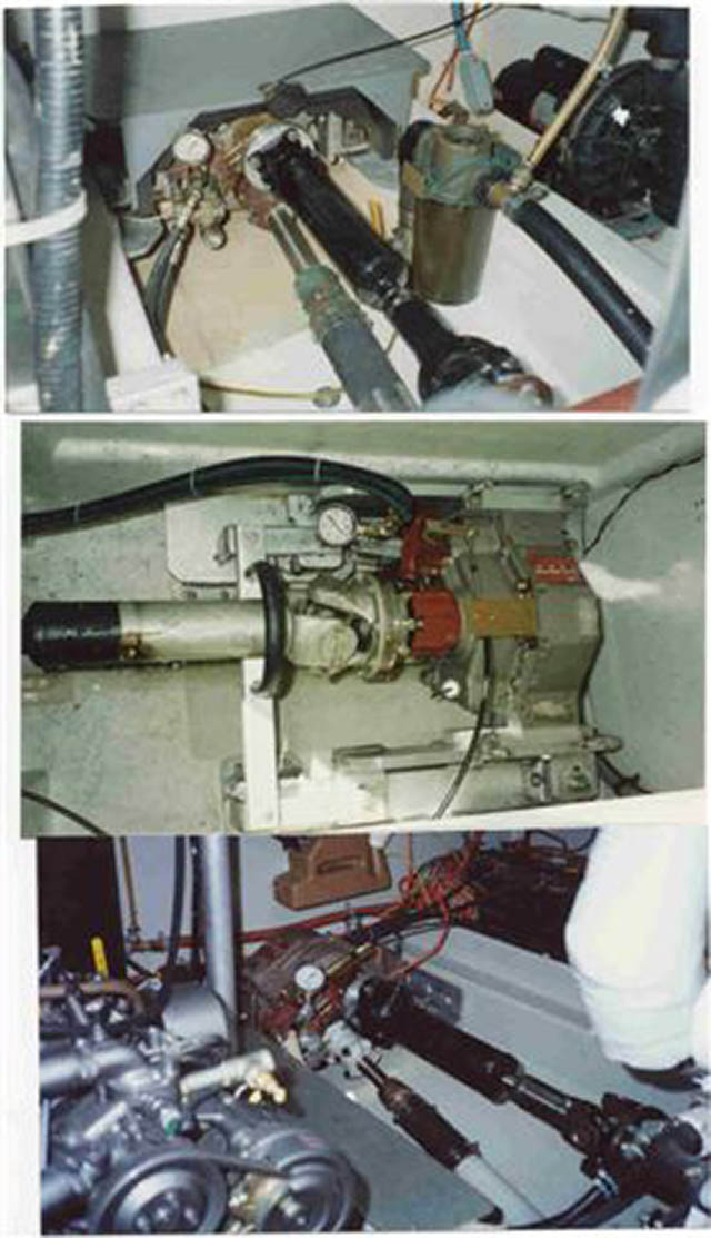
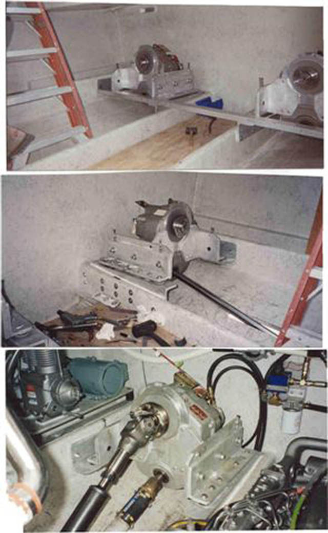
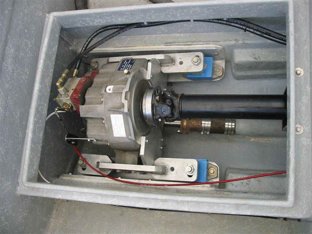
Anyway, look over these pics to get some ideas and a better understanding of the “overall” relationships. Send me some pics of your boat, goals you want to meet, and I’ll forward you some more info specific to what your needs.
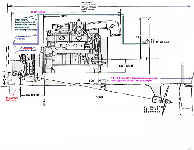
ENGINE-TRANSMISSION-PROPELLER SHAFT DRIVE TYPES
Alignment Methods:
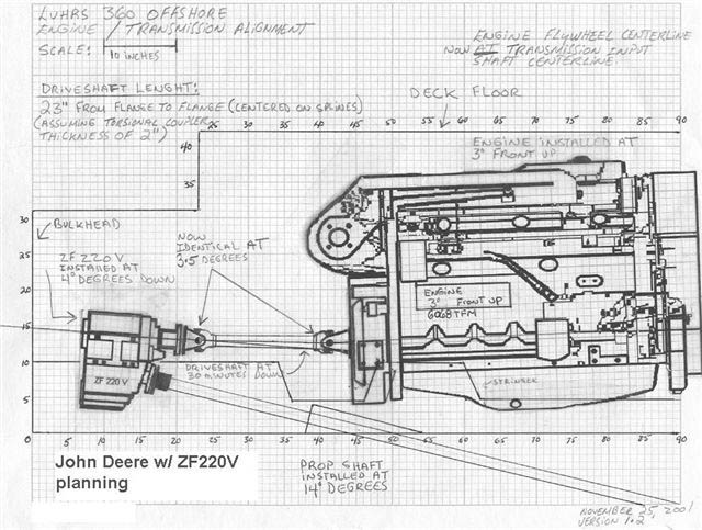
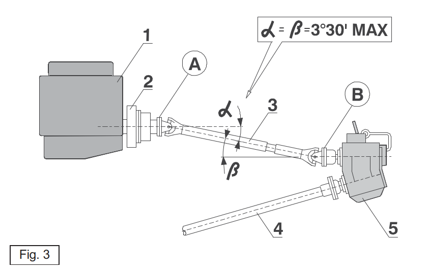
1) V-Drive Alignment method with parallel-face flanges
1. Engine.
2. Flexible coupling.
3. Variable-length universal joint.
Selected according to the instructions of the manufacturer.
In compliance with the installation instructions.
4. Propeller axle.
5. Marine marine gearbox with input and output on the same face.
Caution: Make sure that the longitudinal axes of the flexible coupling, universal joint and marine gearbox input shaft
are aligned on the same vertical plane. The engine and marine gearbox must be installed so that flanges A and B lie parallel to each other.
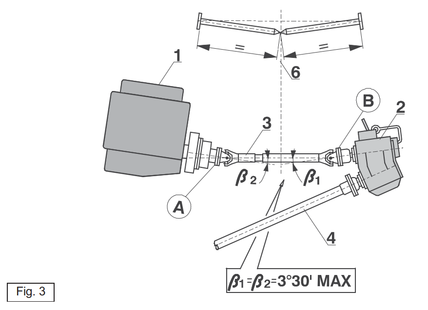
2) V-Drive Alignment method with counterpoint shafts
1. Engine.
2. marine gearbox.
3. Variable-length universal joint.
– Selected according to the instructions of the manufacturer.
– In compliance with the installation instructions.
4. Propeller shaft.
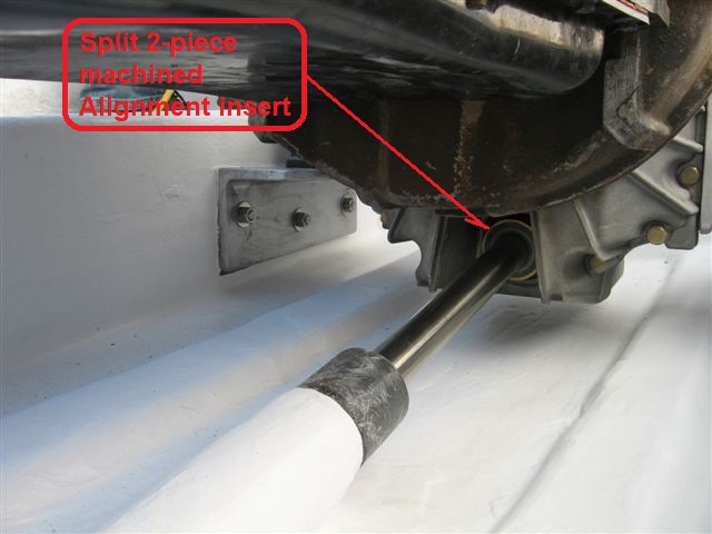
To facilitate the correct alignment of the engine and marine gearbox, that is to obtain identical connection angles
ß1 and ß2:
– install two alignment shafts 6 in place of the universal joint;
– the shafts must have the same length;
– align the two units so that the ends of the shafts meet, to ensure that angles ß1 and ß2 are identical;
– at the end, remove the alignment shafts and install the universal joint;
– make sure that the longitudinal axes of the flexible coupling, alignment shafts and marine gearbox input shaft are
aligned on the same vertical plane.
Caution: Defective alignment can cause irreversible damage to the transmission, noise, vibrations, and damage to the
hull’s sealing systems.
| LONGITUDINAL STATIC |
PITCH MODE | ROLL MODE | |
| ALLOWED INSTALLATION ANGLES DURING NAVIGATION (°)(With reference to the perpendicular and longitudinal axes of the input shaft with respect to the horizontal plane) |
-5 ÷ +10 | -10 ÷ +25 | -15 ÷ +15 |
[hr style="gradient" size="1px"]
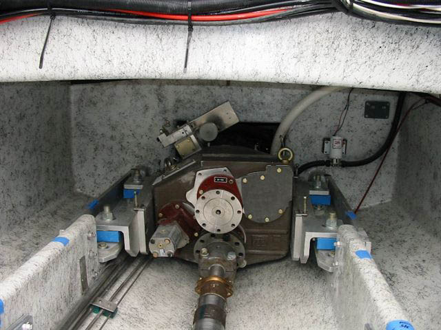
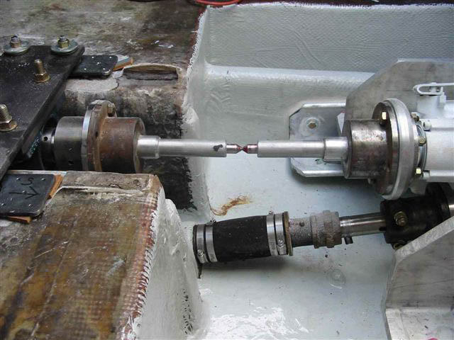
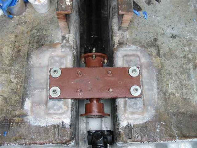
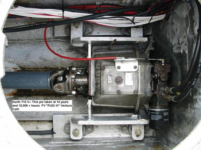
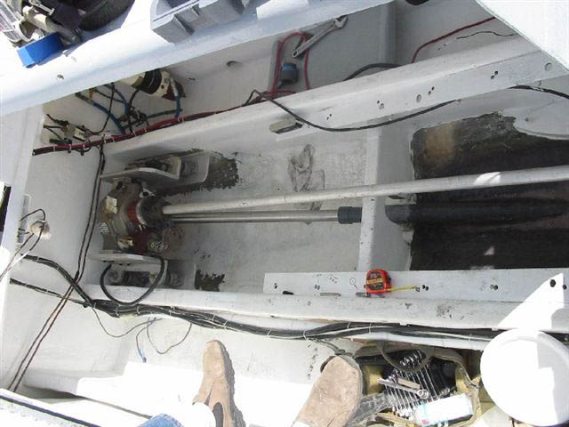
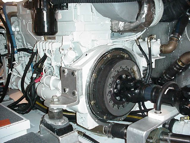
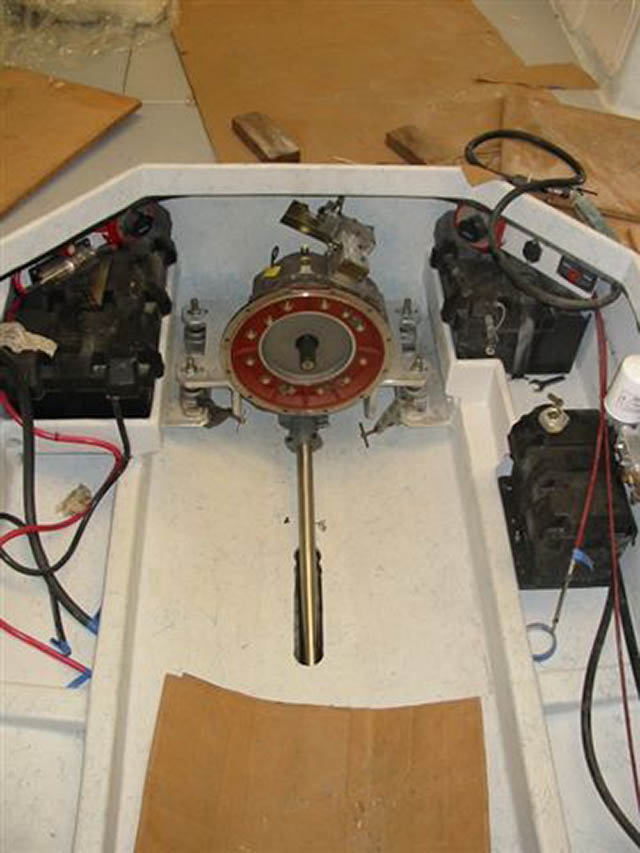
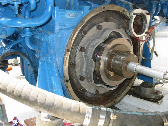
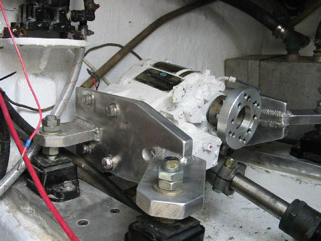
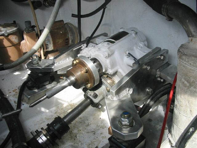
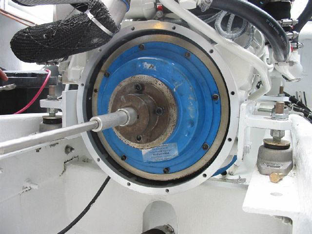
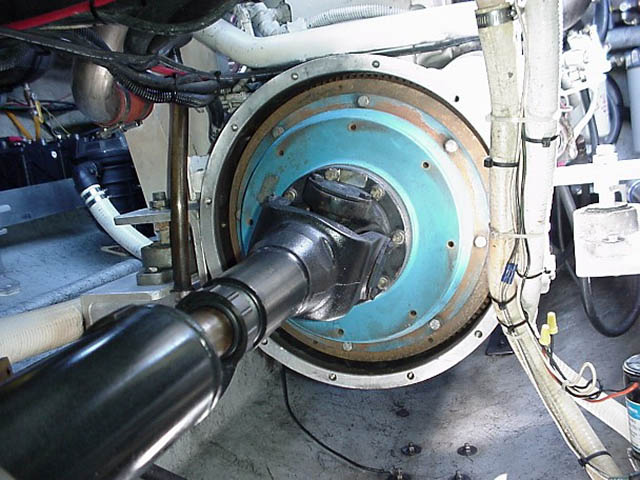
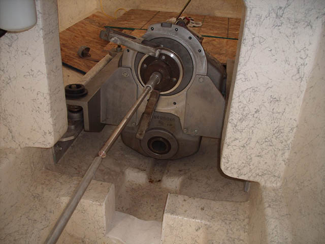
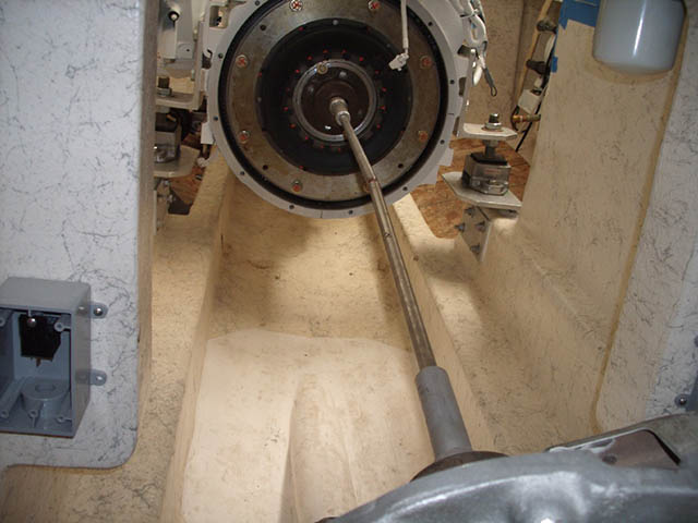
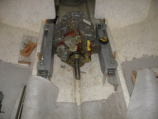
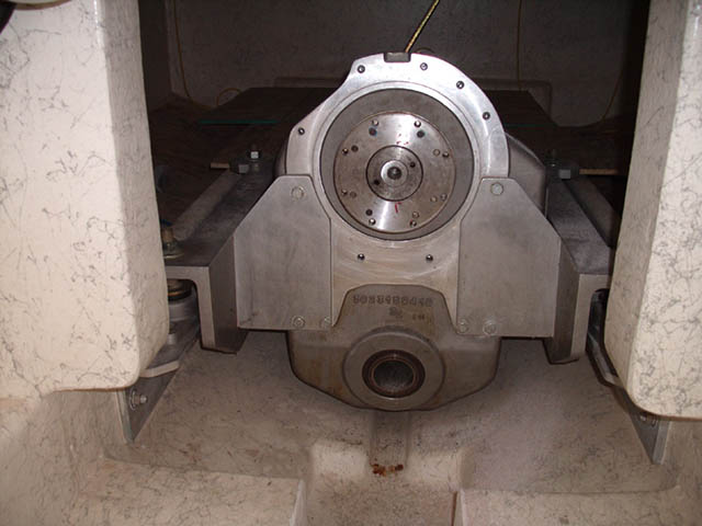
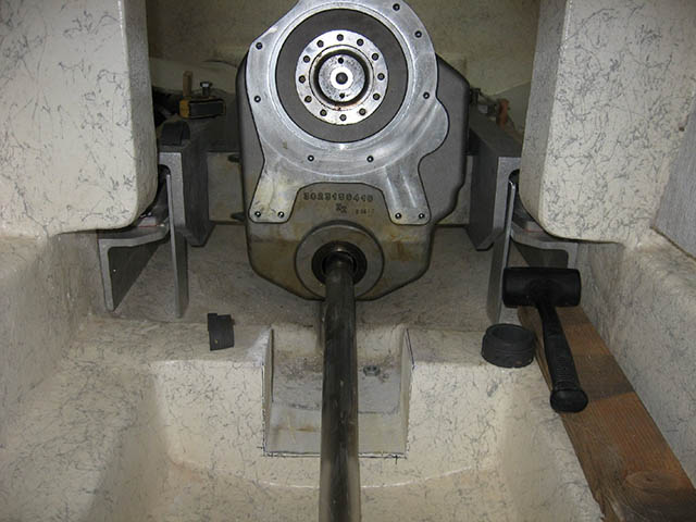
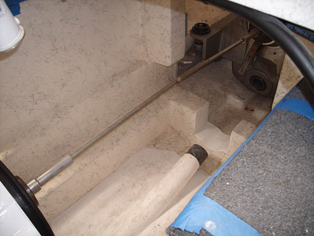
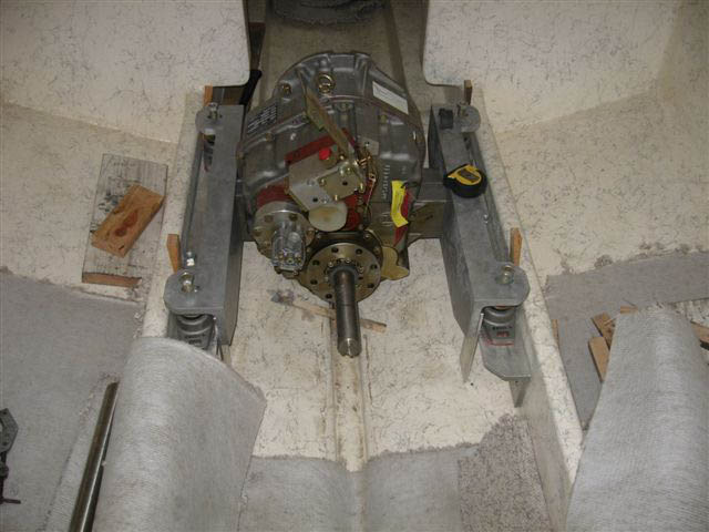
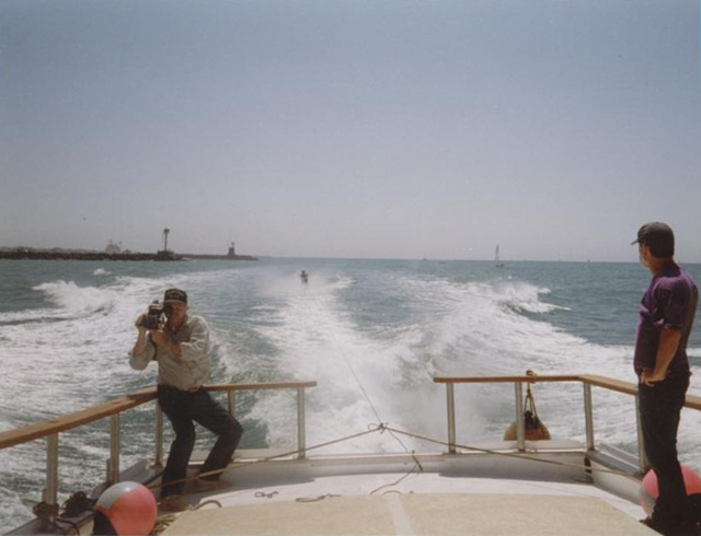
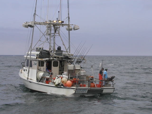
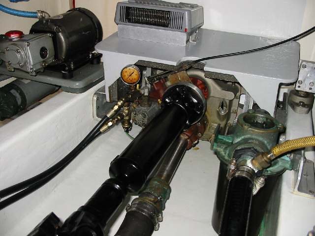
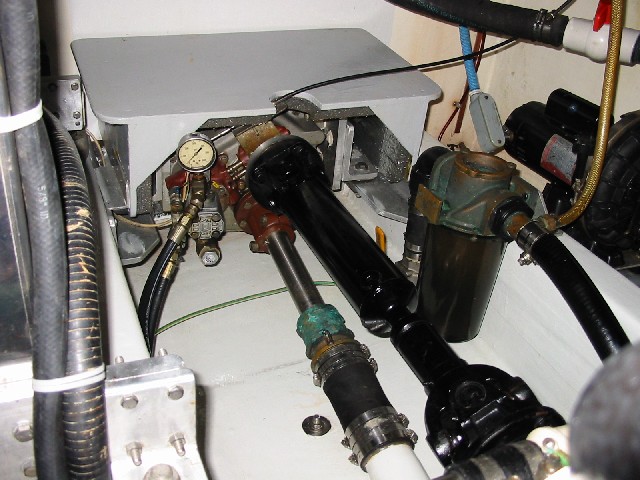
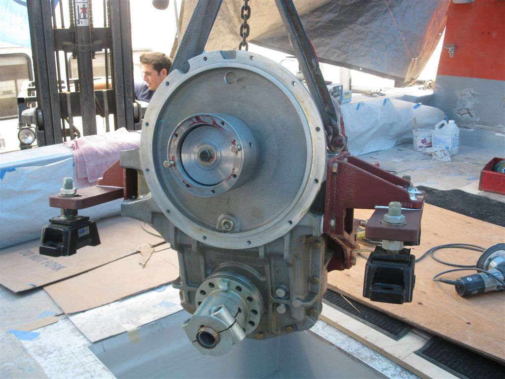
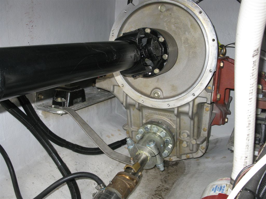
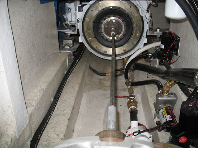
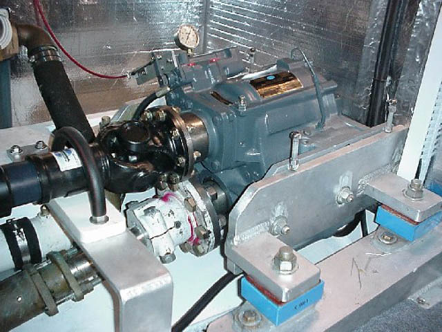
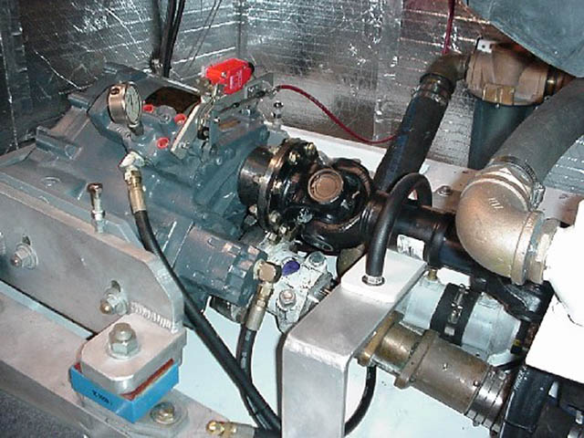
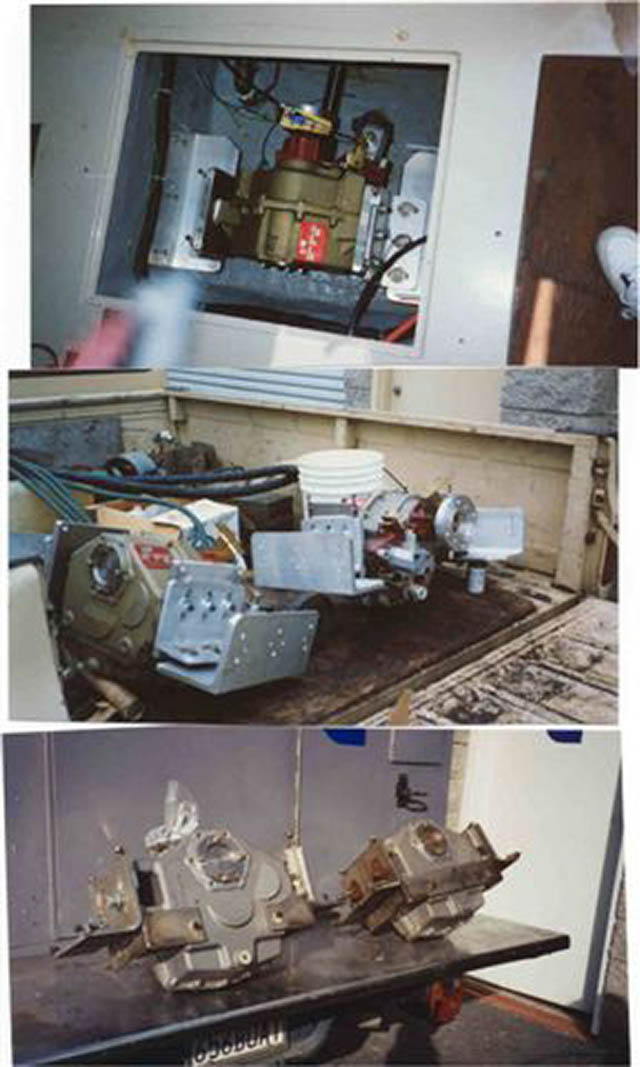
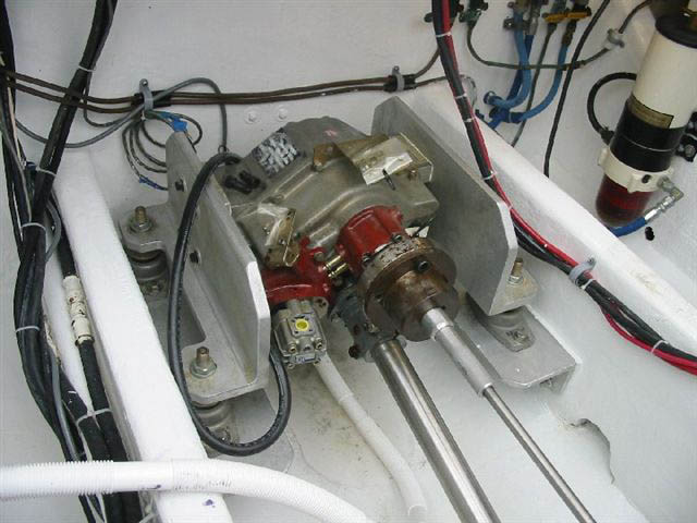
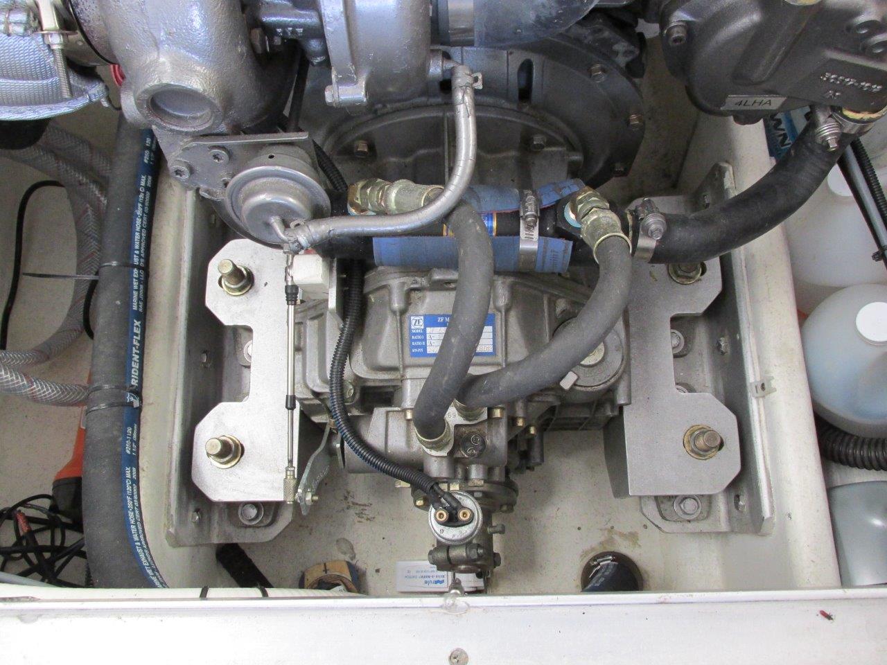
BELOW YOU CAN SEE PHOTOS OF SOME OF OUR INSTALLATIONS