There are no REQUIRED exhaust sizes for Cummins marine engines; there are RECOMMENDED minimum sizes that may or may not meet the required exhaust restriction requirements published by Cummins. Those two statements above are also applicable to most marine engine recommendations / requirements. The sizes that are recommended are based on past experience and are merely a guide in the selection process for designing a safe and non-restrictive exhaust system.
For all of the Cummins marine engines that are in current production, the maximum restriction at rated output is 3″ Hg (about 1½ psi) and I believe this is close to most of the competitive manufactured turbo-charged engines in this 100-1000 hp range.
In most exhaust systems that are in the type of boats discussed in these forums (150-650 HP,) there are TWO distinct parts of the exhaust system/ piping. The DRY part and the WET part. Even on the factory “wet elbows” supplied by all of the manufacturers that I’ve seen, these two sections exist, though many people don’t realize it.. The inner pipe of this “wet elbow” is actually a 90-degree dry bend, or section, surrounded by raw water to keep the surface cool. At the end of this “wet” elbow, where the exhaust hose attaches, is where the water is introduced (hence the term “mixing elbow”) and the exhaust NOW becomes wet. Inside this elbow is a smaller diameter (typically around 2 ½ – 5″ ID) which is the dry side, and where the hose attaches, it expands to (or is surrounded by) 4-8″ tubing/OD piping, depending on the engine size, etc..
When using custom exhaust risers, or most factory supplied wet elbows, the fabricators of these systems employ various techniques to design and build these parts. Some of the designs follow good engineering practices with “thought out” design failure scenarios should the system NOT last the life of the boat. But, MANY do not. In practical thinking about marine exhaust systems, never consider your exhaust riser or wet elbow to be “lifetime.” But, in real life, when most marine exhaust systems fail, (wet type), they lead to contingency damage of various engine parts as the designer DID NOT figure in a failure scenario that would (will) occur from internal corrosion/leaking. This is usually due to the fact that when the “wet side” fails (the failure is often in close proximity to where the salt water is first introduced to the exhaust riser/elbow,) this water ends up in the engine when the owner least suspects it. Internal failure of “wet elbows” and custom water jacketed risers is an old and ongoing problem, regardless of material choice, and/or other claimed construction features.
When building custom wet exhaust systems, these are but a few are of “common sense” guidelines to follow in their design that will help eliminate these types of failures/contingency damages:
- Use all of the available height in the engine room for the riser (where needed and is practical) BEFORE turning over the top and injecting water; i.e. always inject the water on the downhill side, or down stream of the top of the riser. A wet exhaust system with a steep downward slope is always better and safer.
- Always use gravity to your advantage. Water flows downhill so, if you have a system that holds water (water jacketed risers for instance) and this system fails internally (it’s not IF it is going to fail, it’s WHEN it fails,) where will the water go?? Into the turbo/exhaust manifold/cylinders?? Think about YOUR riser or elbow, should it fail internally where you can’t see it., what might happen.
- Be sure that IF the option presents itself in the design of a wet exhaust system, to allow for all of the water to drain itself from the exhaust when not running. Although this can’t always be done, you can still build a safe system by utilizing other simple design ideas, custom mufflers, surge tubes, etc.
- When sizing the system to meet acceptable restriction requirements in order to protect the engine from excessive back pressure, keep bends to a minimum, especially “wet” 90 degree bends. You can assume that, for any given size of piping, a smooth 90 degree “dry” elbow is equal to about 10 feet of the same diameter pipe as far as restriction goes. In some instances, wet 90s could easily be equal to 20 feet of piping when unnecessary water is injected into the exhaust. That brings us to one of the main reasons for this discussion: Exhaust sizes vs. restriction “requirements.”
A typical high performance marine diesel of around 300 HP will pump about 50-70 GPM of salt water through the engine cooling circuit at rated RPM (not necessarily rated HP.) This large amount of water is needed to keep the engine cool and provide for some reserve, but all of this water (excess water) is NOT necessary to inject into the exhaust system to cool the exhaust gases and quiet the exhaust level.. Although most engine installations do indeed inject all of this water, as it “came from the factory that way,” this is not required or necessarily desirable in many installations and repowers.
The mixing of salt water into the very hot exhaust gases accomplishes many things:
It cools the exhaust to levels that are safe (140 deg. F or less) allowing the use of hoses, fiberglass tubing and mufflers, and adds considerably to the quieting and scrubbing process. But it also adds considerably to the restriction of the exhaust system..
Although I’ve talked to “people in the know” that claim the opposite (the exhaust are gases cooled and therefore have less volume,) just believe me that when water is added to 900+++ degree exhaust and steam is produced, that the volume of the mixture of hot gas and water vapor is substantially higher, and therefore needs a much larger exhaust diameter after this mix takes place. This, along with the addition of the water itself and its own frictional resistance and volume within the piping, all add to back pressure and require larger piping than the dry side.. A simple way to see this is by looking at exhaust diameters of typical 300 HP diesels in trucks and comparing them to the typical sizes of a 300 HP marine diesel wet exhaust system.
Now, back to that excess water, and how can we use this water that is needed for the engine cooling but not necessarily needed for the exhaust cooling. First we need to understand how much “excess” there is and then how we use it to our advantage.. Just from testing and building wet and dry exhaust systems for about 20 years in boats, I’ve learned that you need to inject between ¾ and 1½ GPM of water flow per 10 HP into most any properly designed mixing elbow/wet exhaust system to allow for more than adequate cooling and silencing of the system.. By putting a simple “T” in the hose after the heat exchanger that goes between it and the mixing elbow, and then allowing the proper amount of water to flow out the side or back of the boat freely, one can reduce back pressure by a measurable margin, and now, in many cases, use smaller than recommended sizes of exhaust hose and/ or components and still meet restriction requirements.
From direct experience, I’ve used 5″ wet on 450 C’s and 4½” wet on 330 Diamonds and still was able to be well under restriction limits at rated HP and RPM. In quite a few of the repowers I run into, we are going from a gas motor w/ around 3 ½ or 4″ exhaust size, and the recommended size for the new diesel may be 6″.. This can be a tough one in many instances (space and cost limitations) and with some clever engineering, I’ve always been able to use 5″, or even less in some cases.. There are many factors involved in this selection of smaller sizes, and only with experience to draw from, can all of needed design features be put together in a way that will insure a safe, but non-restrictive exhaust system. As to having to use 8″ exhaust on the Cummins 450C (mentioned in a post on the Volvo 70’s forum last week); only in an exhaust system with a design that gave little thought about all of the options which could be used to lower restriction, would an 8″ exhaust size be needed. Never have I had to use an 8″ exhaust on this engine to meet restriction requirements.
Please don’t take the above to mean that I don’t use 5″, 6″ or even 8″ systems. I’m only trying to help with some of the repowers that come up where the recommended exhaust sizes DON’T fit the constraints of the boat or maybe the pocket book. It takes very careful planning to reduce from the recommended sizes but this alternative is there, if the design is right. There are many other tricks to reducing restriction in wet exhaust systems and these may include coring a hole through the first input baffle inside a typical inline muffler, enlarging spigot sizes on both the input and the output of an existing 4″ or 5″ muffler to the next larger size, etc. etc. etc. Again, these all come from past experience and field trials along with some good solid engineering.
And, as one added feature with bypassing some water out the side of the boat, you will get a easy “visual” of this water flow, and on boats w/ swim steps and stern exhaust, seeing this water flow can add a feeling of comfort knowing that you are pumping lots of seawater.
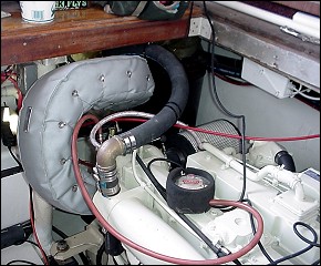
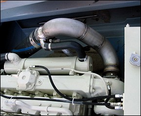
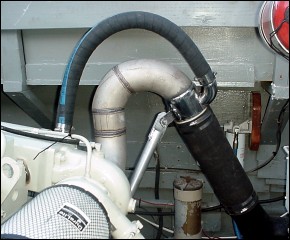
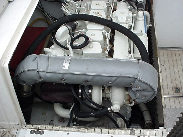
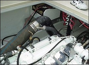
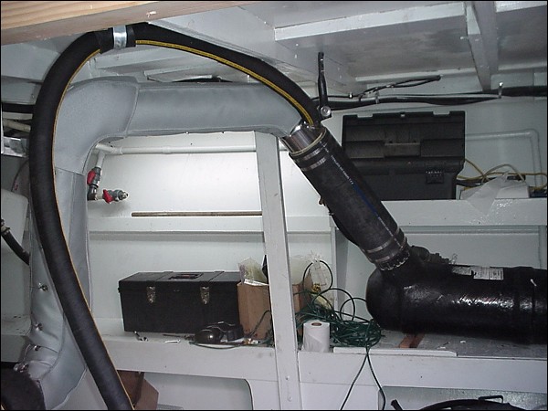
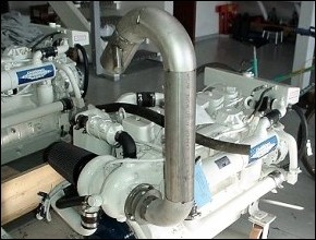
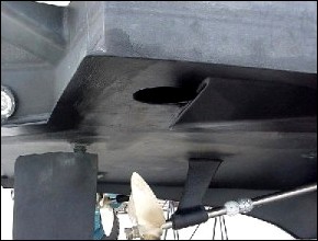
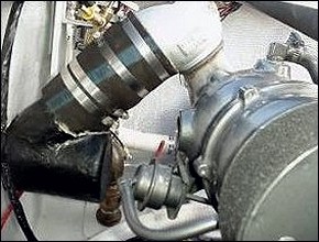
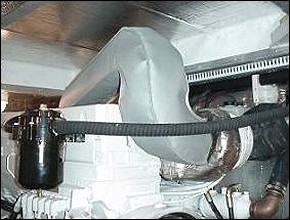
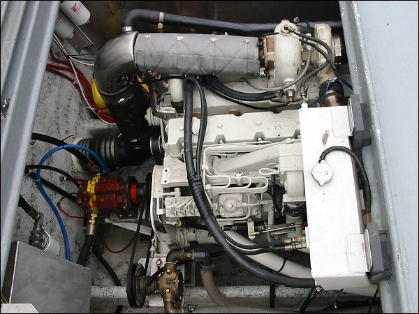
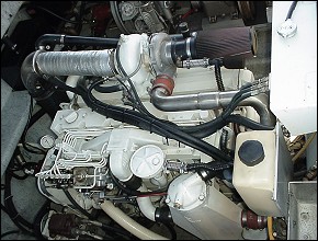
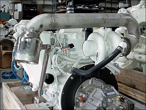
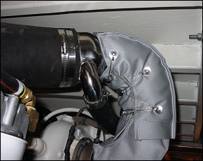
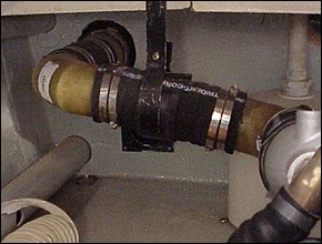
The pics below show some designs that have accomplished the features mentioned above and were made to “fit the boat”, the requirements of the applicable engine manufacturer, and used “common sense” as a component of the design.
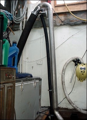
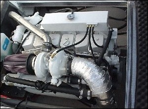
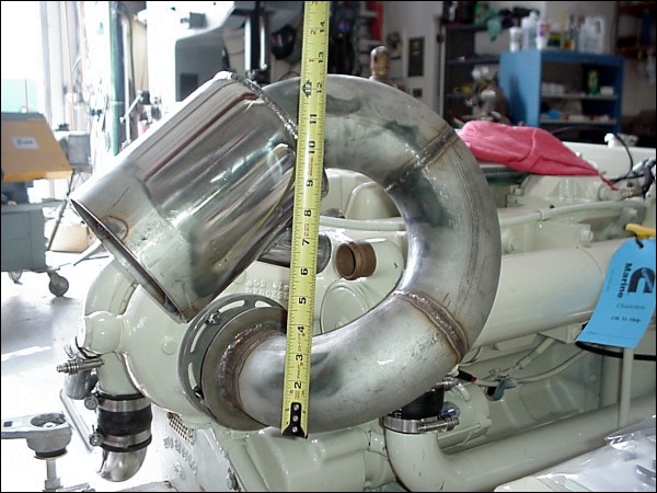
The top of this engine is 18″ below the waterline “static”
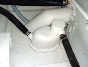
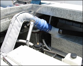
The pics below show some designs that have accomplished the features mentioned above and were made to “fit the boat”, the requirements of the applicable engine manufacturer, and used “common sense” as a component of the design.
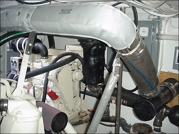
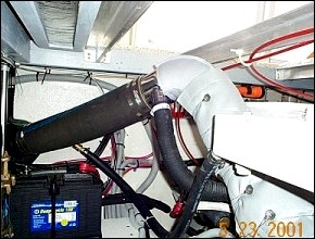
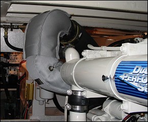
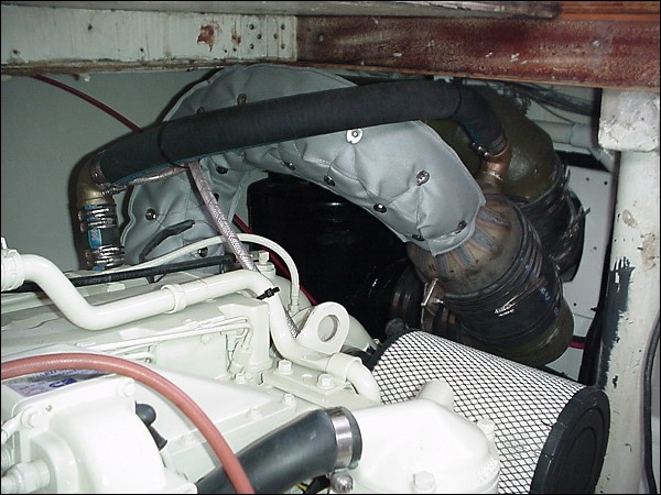
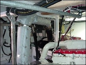
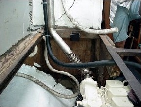
Starboard Riser for Bertram 31

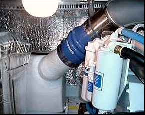
Vdrive shown above
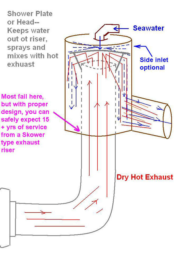
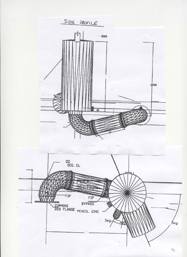
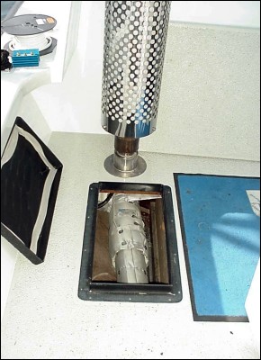
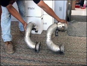
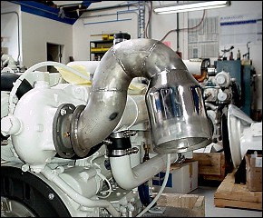
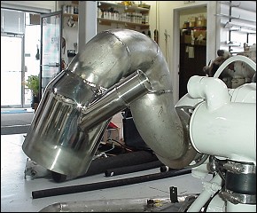
Shower Type Exhaust Riser