 Yes, you probably already understand hydraulic steering, but I think I may look at hydraulic steering a tad different than most do. Since my approx 36 years experience with hydraulic steering is generally on vessels under 90 ft in length (ZERO Mega Yachts), let’s look at my input as being applicable to boats in that size (& price) range. First we’ll talk about the basic components and how they work in the system (both “passive” & “power” or powers assisted steering) . I’ll start with the COMPONENTS that make up a typical hydraulic steering system…
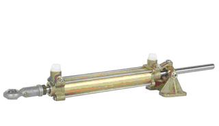
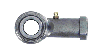
The Steering Ram
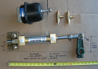
 The ram is really the key part or “foundation” of the steering system (in so many words, the “RAM” carries the load). The helm pump (at the other end) is just the fluid “pumper” and does not carry the load except while actually turning the rudder. Once the rudder is static, regardless of its actual position, the ram and steering lines (up to the check valves in the helm pump) are carrying the load, or pressures, developed in the system (the rudder is always being pushed, one way or another, from the vessel movement and / or water movement around or past it.. Even a very small & inexpensive helm pump could turn a very big rudder on a large vessel quite easily (as long as one is willing to put up with enough turns “lock to lock” which is really where the mechanical advantage comes from), but this is not always a practical solution. As to selecting a RAM as to its base quality, to us this is a no-brainer.. Brass, Bronze, and Stainless Steels alloys are the only acceptable materials that should be used for the construction of any RAM that even gets close to saltwater, or is used on any type of vessel larger than a run-about . Aluminum has no place in Hydraulic Steering RAM construction except (maybe) for fresh water use and super light duty applications.
The internal & external size of a ram is measured in a few ways—Common terms:
- BORE: The piston bore diameter—Inches or in millimeters—common sizes might be 1.25”, 1.5”, 1.75” and 2”
- STROKE: The total travel of the ram – 7” and 9” seem to be most common, but ram strokes come from about 5” to about 12”
- DISPLACEMENT: This is the mathematical computation of the bore and stroke measurements less the volume of the rod itself. This is the most important number as it tells you the relationship you will have with the helm pump as to how many turns the pump will have to make in order to move the ram a full stroke. An example—A 1.5” bore ram with a 7” stroke might have a internal displacement of 10 cubic inches; A typical helm pump may have a internal displacement of 2 cubic inches ( or 35 cc’s) per revolution.. This would mean that it takes approx 5 complete turns of the helm pump to move the ram its 7” of travel.. But in reality, always add about 10% to computed turns vs the real number you will end up with.. Why (?) , because of internal hydraulic slippage that is always part of any hydraulic system that uses fluid to move something
The Helm Pump
When we talk about a helm pump, we must also talk about both passive and power steering as that is the part of the system that interacts most with YOU and the rest of the steering system. Most passive (non-power assisted) systems are set up to be between 5 & 10 turns lock-to-lock on the steering wheel and if we translate into to mechanical advantage, it goes like this—We’ll use total rudder arc at 70 degrees (about 1/5th of a full circle and seems most typical in most steering installation guides) for this example– If it takes 7 full 360 degree turns of the steering wheel to give full stroke or full rudder travel, then you have about a 36:1 gear (actually hydraulic) ratio between the two.. All else being equal, most steering systems fall in the 20:1 to 40:1 ratio range. Think about it—you just went through 7 x 360 degrees of helm pump rotation (2520 total rotational degrees) , but the rudder only rotated 70 degrees of total arc; hence a 36:1 ratio, “on paper”(we’ll get to that later) between you (the steering wheel) and the rudder. Bet you never thought about it that way before!
I also need to mention that with passive steering you have both pressurized 3-line systems and non-pressurized 2-line systems.. There are some that think “pressurized” has something to do with power steering, but it does not. Hynautic (no longer as they were bought by Teleflex) invented the 3-line pressurized system for one reason—to make it simple to bleed and fill and to allow a less critical installation as to elevations of components, etc.. “gravity” was not a concern with the pressurized systems. But with that, they added something that most don’t know.. Usually a much higher steering effort because of an added complexity of more lines and valves.. Comes down to internal friction that is created when pushing fluid through hose, pipes and fittings..
In a pressurized 3-line system, you typically have between 15 & 25 PSI at all times in the reservoir, “third line and the low pressure side of the pump. In a 2-line non-pressurized system (although you may still have a 3rd line), the reservoir and / or low pressure side on the system is at atmospheric pressure and relays on gravity and height to keep the flows right between multiple stations. That’s also why you can use clear vinyl tubing for supplying fluid between stations and or reservoirs..
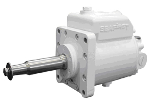
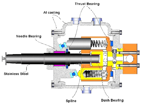
Construction materials and base designs used in helm pumps can vary and there are many that have withstood the test of time. In the past, Wagner was the accepted standard for pump designs on vessels up to about 100FT. Other dominant names are Teleflex / Capilano, Hynautic, Jastram, Vetus (mostly Italian made systems), LS (French made), Seafirst (Korean) and a few others. All of these manufacturers employ some unique designs and all have, what we feel, are both good & not so good, features that would lead us to choose one particular Helm Pump over another for an specific application. Most helm pumps use aluminum for the housing and some other components with Stainless Steel are used for the shaft. Inside the pump, most designs employ a multiple piston pump on an angled squash plate. There are even variable displacement pumps that vary the angle of the plate to change piston travel, thus the internal displacement of the pump.. This allows “tuning of the system” for either easier steering effort (more turns L to L) or faster steering (less turns L to L — increased steering effort).
Is Power Steering for you?
With power steering you have a 2nd hydraulic pump that is driven by an external power source (an engine or electric motor, not just your arm), and through a series shuttles block or pilot operated valves, hoses, etc, the output of this secondary pump is fed into the steering system to SUPPLEMENT the mechanical or “arm driven” passive helm pump. In just about all cases, with power steering, you have less turns lock to lock and the steering effort or “rim force” ( we’ll talk about that term later) is reduced, and many times, to a “finger force” steering effort. But this increased mechanical advantage does come with an additional price—Added input power is needed (typically ½-3 HP) which equals a small increase in fuel consumption, along with the added expense and additional equipment needed to make it all work & maintain. You must decide if power or passive steering is right for your application, understanding that the biggest difference will be turns lock-to-lock, the amount of effort to turn the steering wheel, and, the amount of monkey motions you want to deal with. From working with power steering systems in marine applications for about three decades, one thing I have learned is that most smaller systems (maybe on 30-50 ft vessels) that I have come in contact with tend to be designed with too large of a power driven pump (too many GPM) in relation to what actually needs to be done, and the result is usually excess heat developing in the system, or the system is noisy (the pressure or flow bypass valves in the system are continually working making noise)…But, still a power assisted system can be the best choice for many applications where excessive force is required to turn the steering wheel or one needs very few turns ( maybe 2-3 max) from lock-to-lock on the steering wheel. Maybe the lobster boat that needs to pull upwards of 300 traps per day and really needs quick and extra easy steering??


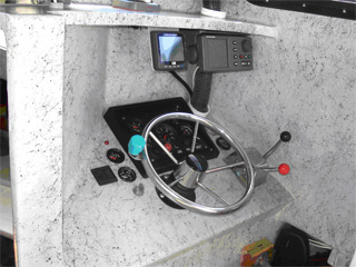
Steering Wheels
Believe it or not, most people do not completely understand the full role of how the steering wheel (its diameter and placement) plays into how the steering system works. Usually “aesthetics” is the basis to decide what type of steering wheel one chooses.. Yes, that is important, BUT, the diameter of your steering wheel or the actual radius at which you are turning it becomes a major part of the equation if you go with passive steering.. Bigger diameter wheels equals less RIM FORCE in order to turn.. Think of it like a longer wrench when trying to get a bolt tight, or loose. Call it “LEVERAGE”. If you only have room for a small diameter steering wheel, then in most cases, you will need more turns lock-to-lock to compensate for the decreased leverage you have turning the wheel. Large diameter steering wheels give the operator more leverage to overcome higher pressures within the system and usually require less turns lock-to-lock overall…
Steering Lines & Fittings
Here is where you will see major differences in what is used or can be used in hydraulic steering installations. Most smaller “production boats ( from 18 ft outboard powered boats to 40 ft lower cost diesel powered boats) usually employ common type brass pipe and tubing compression type tubing fittings and un-reinforced thermoplastic hose. Most get by with this type of lower cost equipment, but realize that you get what you pay for.. Most of these systems are “barely adequate” as to performance and overall system longevity and we consider the use of un-reinforced thermoplastic tubing (typically nylon) to be applicable only to “lake boats” and outboard engines at best.. IMO, using SAE or JIC flare fittings with copper or metallic tubing or pipe, or in combo with reinforced non-metallic hose is the right solution for all marine applications. You must also be careful about using any type of brass fittings that are not rated for working pressures of at least 1000 PSI, and are robust in wall thickness especially with internal threads. Assembly should be done using high quality pipe dopes, Anaerobic sealants, & sometimes even epoxy compounds specifically made to withstand petroleum based liquids and are designed for pressures of more than 2000 PSI. Avoid Teflon tapes entirely as you do not want any shredded pieces getting inside the system
Passive steering system pressures should be designed so that 90% of the time, line pressures fall under 500 PSI. This is determined by RAM SELECTION or size.. Larger displacement rams make for more turns but also keep pressures low. Steering wheel or RIM force becomes uncomfortable much above 5-8 lbs, so sizing the ram to keep pressures low means less rim force or effort to turn the steering wheel…
With power steering, pressures are usually higher and can play havoc with a ram if undersized. The operator, typically, never knows the difference until something back by the rudder breaks.. Sized right though, power assisted steering is sometimes the only practical choice when the operator wants 2-4 turns lock-to-lock and needs a small diameter steering wheel.

Hydraulic Friction and the “LOSSES” you can feel
This is usually why most passive systems are hard to turn even at the dock, plus it is something that most, including many builders and seasoned operators that have been around for decades, have no clue about–This is caused by, in so many words, “poor plumbing” design– from small ID lines, lots of 90 degree elbows and little fittings, to using a high viscosity steering fluid and unneeded friction or binding of the rudder or other mechanical components. It’s so prevalent in the boating industry that it’s just an accepted thing like “that’s just the way it is” when you don’t have power steering…. 110% WRONG !! We’ll get to that later
Hydraulic Noise
In power steering systems, hydraulic noise is from the hydraulic fluid being pushed too hard and too fast.. Too “HARD” comes from too high of pressures in the system meaning that the ram is undersized or the pump is too large causing the relief valve is continuously by-pass. “Too FAST” means line sizes are too small and or / and pump capacity is oversized— Both inter-react and both cause noise and heat, besides sucking up power from the engine. A typical hydraulic steering system on a 50-60 Ft and under vessel only needs about 1 HP or less to do the job.. Your arm is (maybe) 1/20 of a HP, so you can see that 1 HP is all you should need.
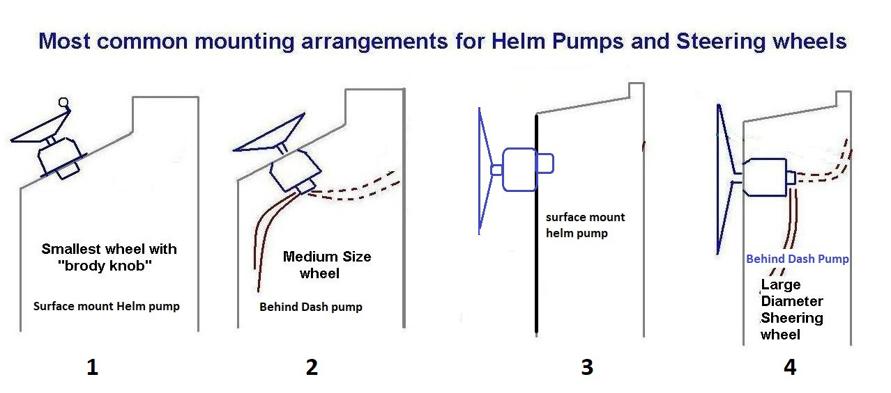
Smaller steering wheels
(maybe a 7-9” radius) with a “brodie knob,” and installed “bus like” or somewhat on a flat or tilted position in a boat, can do a great job making 6-10 turns lock-to-lock seem simple. On the other hand, a more traditional steering wheel arrangement using a 24 -30″ Diameter wheel is typically not easy to deal with when over 3-4 turns lock-to-lock.
Typically, most hydraulic lines run somewhat down and to one side of the vessel when they leave the helm pump… if we can have only one outlet, then “down” would be preferred as long as we have clearance for a 45 or 90 degree adapter. Using a 45 or 90 degree adapter on the back will also work. With two stations (also common) having both bottom and back connections is nice and eliminates much of the plumbing and connections.
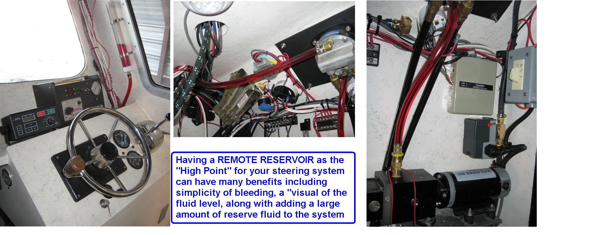
Some other desirable features that you may want to consider when putting together your hydraulic steering system: Consider adding “Tee’s” on the pressure lines in a convenient spot should you wish (someday) to install an autopilot. You might even consider a remote non- pressurized reservoir that is the “high point” of the system. This allow for an easier fill, adds more fluid for the system (in case you develop a leak) and will give you a “visual” of the level.. But, having a “bottle” of hydraulic steering fluid hooked up to your system is not always an aesthetic or practical thing to have on many vessels. Some commercial style vessels put a remote bottle high up on the mast tower to add some “head pressure” to the system.. Works really good.
When choosing a ram or trying to come up with a tie rod for twin rudders, look for a ram with a SS ball joint instead of an old fashioned clevis.. Makes for a much better and easier install and can eliminate the “play” that usually comes with a clevis pin.
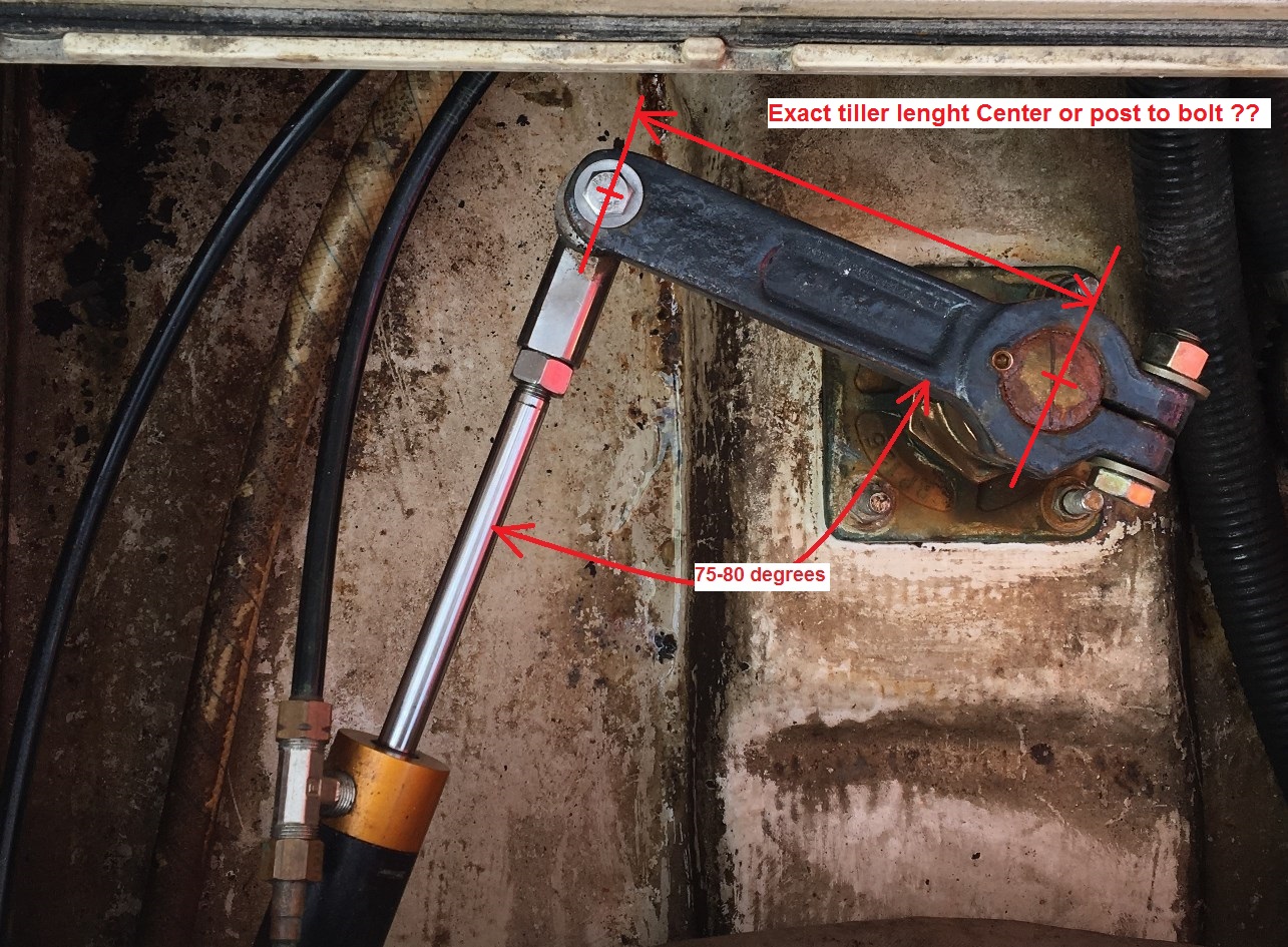
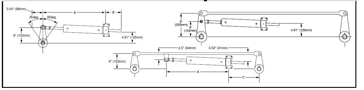
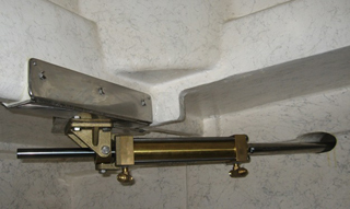
Basic Ram to Rudder Geometry
Setting up your ram for the correct steering geometry is easy as long as you follow the simple rules of rudder arc and how the tiller moves during the swing from side to side. Anywhere from 70 degrees to 90 degrees of total arc is common, but we tend to lean toward 90 degree of total arc on single engine boats for better control at docking speeds and 70 degrees of arc on twin engine boats.
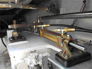
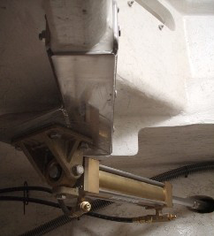
Mounting the Ram
Always think heavy duty when mounting the ram to the vessel, spreading the “Push & Pull” loads between the rudder shaft and vessel framing is always best. When using aluminum and brass, always use a piece of hard non-metallic material in between the two metals w/ plenty of grease on all surfaces when putting it all together, then 10-15 years down the road, things will still be nice if you have to take something apart.
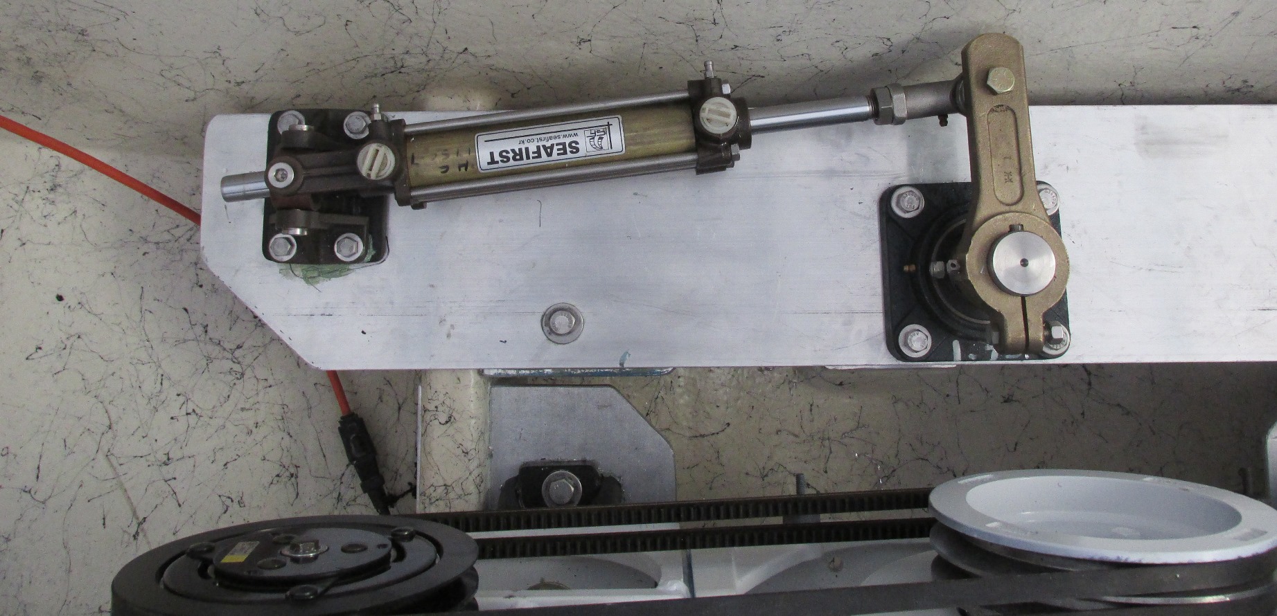
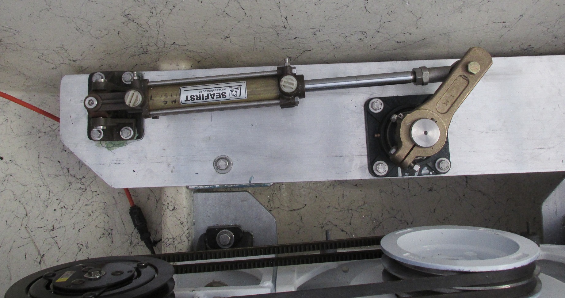
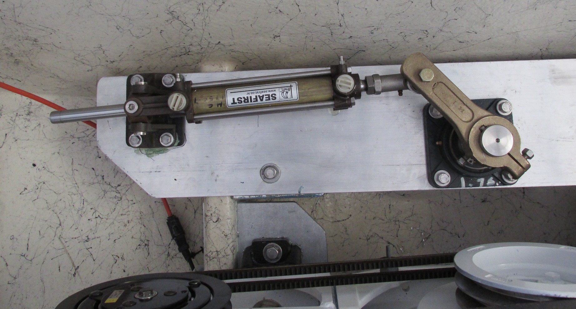
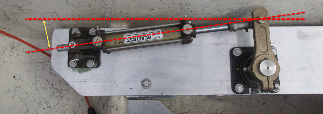
Shown above is the correct layout or geometry of the ram to rudder relationship IF you were using a 7” stroke ram and needed a total rudder arc of 70 degrees. Below is the same ram setup if you wanted a 90 degree rudder, or a 45 degree swing to either side. Note that the tiller arm length is about 2” less. If you were using a helm with this cylinder with a 2 cubic inch per revolution output, you’d have about 5.5 turns lock to lock.. BUT, the rudder would move farther per turn with the 90 degree setup yielding faster steering. Net result: less leverage, but faster steering and in some cases, better low speed control because of the increased rudder angle. It all comes down to “balance” of your components to yield what is right for your particular needs.

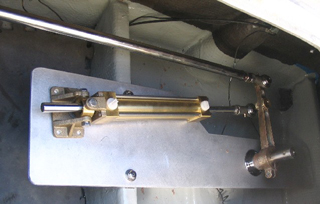
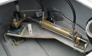
Be creative when designing a very solid ram mounting when angles and mounting surfaces are out of the norm. Using Epoxy and stainless steel there are lots of solutions.
I will also touch on more items that can really make your steering feel “easy and light” (non-power steering). Try to use as few 90 degree fittings on the pressure side and keep line sizes as large an I.D. as practical. For helm pumps in the 1.5 to 3 cu-in per revolution size range, 5/16″ or 3/8″ ID lines are best. Once you get above that , 3.5 cu in to 6 cu in, then 1/2″ I.D. is a must. Refrigeration copper is always a good choice if you know how to work with it.. Sch 40 SS piping or epoxy/plastic coated “gas piping” is also great when we get into 50+ ft vessels.
The Importance of the Steering Ram Mounting Offset
Mounting the ram in such a way so you never experience a rudder FOLD-OVER requires that you incorporate the proper mounting offset angle as it relates to the ram to tiller geometry. This will prevent over-stressing the components of the steering system and will always allow enough mechanical leverage to have a completely “safe” setup.
Steering Fluids
Lighter viscosity fluids just about always make for easier steering.. ATF (Dextron) works well in some systems, but if thinned down to about ISO 15 (using very clean #2 diesel — about 3 parts ATF and 1 part #2) you have a very inexpensive, proven steering fluid that will never give you issues when using the system designed around light oils (Hynautic, Wagner, Seastar, and some others).
I hope this helps, and now that you know the “basics,” feel free to contact us for some “one-on-one” if you are contemplating going hydraulic or need to upgrade an older system. We speak the language of marine hydraulic steering very well…