


Introduction
Replacing a propeller shaft, shaft log, strut, or rudder, one at a time is a fairly straight forward job as you have a “given” as to exactly where one of these pieces is supposed to end up and probably what it looked like in its original form. If a shaft log is in place or still part of the vessel, its angle is fixed and both the engine and strut must be in line with it. If the strut is in place, then the log must be installed in-line with it. Pretty simple, when you think about it, as there isn’t much to think about; it’s all been done for you before. What this article is about, is when you are starting with NOTHING but a bare hull/engine room stringers that generally will only tell you about where the engine / transmission will go or be situated in the vessel. Now you are scratching your head.
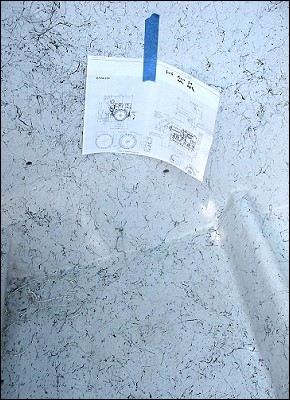
The images here are really the bulk of this article, as “they say” what is hard to put into words, by showing the basic sequence of events that need to take place. All of these types of jobs must start on the drawing board though, but this does not mean “AutoCAD” or ?, just a basic drafting board and the most basic drafting tools along with manufacturers drawing
Armed with this now, the person overseeing the work must also possess the knowledge to select not only the right engine/trans combo, he needs to know the diameter of the prop, shaft size, the general location and dimensions of the rudder. Basically, these major components must be decided BEFORE you hit the drawing board. Yes, it is during this initial layout and planning period that you may find that an initial selection of a particular transmission may not allow the engine to clear the underside of the deck, or it may hit the bottom of the boat.. It is much easier to “erase” and re-think a selection now than after your purchase. Where I see most of the problems in this area of the planning is with purchasing an engine/trans combo with the lack of (enough) down angle, or whether it’s an older style coax-type gear (like a Twin Disc MG 506 or 507) that typically need more clearances to get them to fit. Because of the many varieties in transmission design, this has made it more complex as to choosing the right gear, but also has given us the flexibility to do a “better fit” job. I think the biggest innovation in marine gears was the “down angle” design, initially introduced w/ the early Twin Disc MG502A, but highly popularized by the IRM220A w/ a built-in 10 degree down angle (now called the ZF220A) about 20+ years ago. To this day, this basic design has been adapted to most installations and continues to evolve into marine gears with ratings to well over 1000 HP. I’m still waiting for a 12 degree down angle gear as this would even be better in some installs/designs. But, that’s why we are still in this “drawing stage”.
I use a small 30+ year old drafting machine (you know the ones with arms and a protractor angle “Vemco” type) on a regular table. I draw at 1 to 2″ per ft scale and have found that one can easily get everything in place to within 1/2″ or so, including the final shaft length. As the actual install progresses, some parts of the job are more easily figured out at that time instead of attempting to draw them. The “drafting work” is more of (what I call) a POINT drawing, in that it tells me the major positions and clearance I need to make it all fit. This is not supposed to be hi-tech, just common sense using basic high school skills mixed in with past experience. Also, keep in mind that this is not a production boat – These are all “ones-offs”, as what applies to measurements on this boat will most likely never apply again. You also find on twin engine boats, that “adjustments” may need to be made as to “final” position on some components due to the irregularities in vessel hull construction, between port and starboard sides.
Doing this work is not for most “first timers” as good skills in glass work and / or metal fabrication work are needed along with the foresight as to how each small position change will affect another part of the entire shaft/log/strut/final engine-trans position. But I hope the pictures presented here will help someone do this with a better understanding of the over-all job involved.
Getting Started
We now know what engine/trans combo we are using. We have our vessel ready to start the install and we have figured out that what we are really trying to do is utilize the space most effectively between the front engine room bulk head and the transom of the vessel. Very simple if you just start at both ends and fill in the center. We typically put the rudder as far aft as possible, and many times, even install it BEHIND the transom so as to allow more prop, less shaft angle, etc.. We have our boat blocked level side to side (very important w/ twins) and at a height to allow enough clearance to install the shaft under it. We have our drawing at hand, and we have our initial lay out tools — tape, chalk line, straight edges, Sharpies, cordless drill, jig saw/Sawzall, hole saws, etc.. Next will come some drawn lines – finding the “centers”, front of engine room and rear of engine room. Got to get some basic lines drawn out so we can figure out where to start cutting.
Transmission
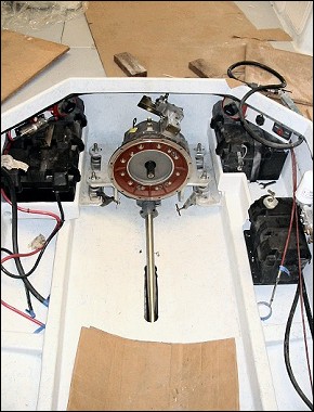
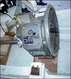
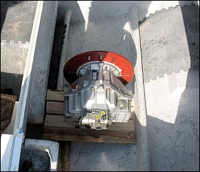
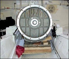
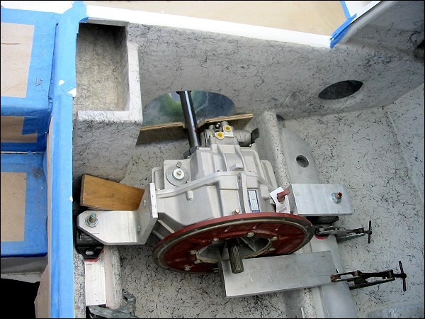
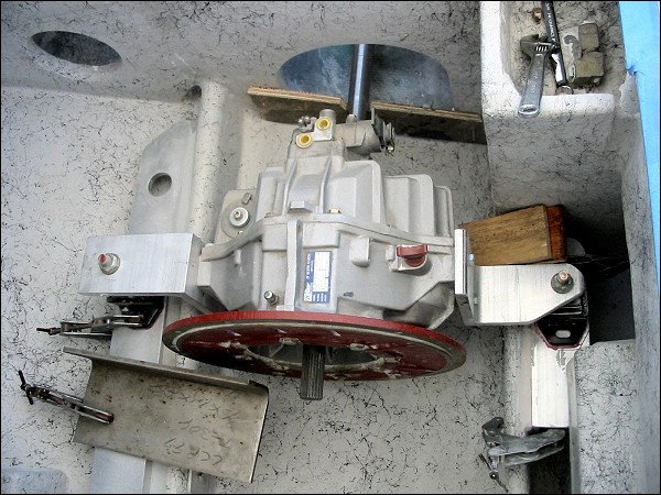
Now comes the fun part, and what I feel is the real start of the job – WE ALWAYS start by lifting in the transmission first. Inline or V-drive-makes no difference. We do this with 500 lb gears or 150 lb gears as this is the most accurate jig you can use. Easy to do, easy to work around and, again, it is dead accurate and will allow you to position everything, including engine mounts/brackets, rails, shaft log, strut, rudder, etc. exactly where they need to be. In well over 200 repowers, I can only think of twice that I have ever lifted in an engine during the install, used it for measuring, and then removed it.. It can ALL be done with just the gear 99% of the time and it is so much easier.
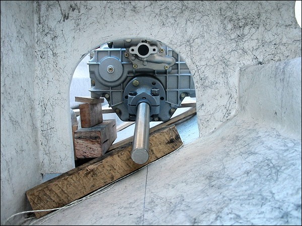
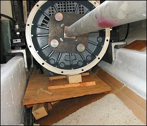
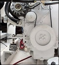
Once the gear is in the general location, we used wood pieces and wedges to get it to a “close” location. Sometimes we will use a small “A” frame to assist. Some more measuring now, using our drawings and a digital level – Forgot to mention that if you want to do this type of work, this is a must – ( about $150) certainly has made my life easy and increased the quality of my work. Notice the “tube jig” on the transmission input shaft – That’s the ENGINE CRANKSHAFT and with that, now we can really figure out how this engine/trans package is going to fit. Yes, we use an accurately machined jig for this and have adapters for gears up to ZF 320A’s and others. But luckily, many of the gears share the same input splines, so this makes it easier. With remote V-drive work, we have made jigs to 8 ft long using this same technique – extremely accurate.
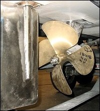
With the transmission now positioned very close to what our drawing said, and we have now confirmed our engine clearances, we recheck our angle(s) using our digital level. BTW, these “angles” are always a “relative angle” to the boat bottom, and not to “earth level”. In this case (and most of these types of installs), we shoot for a relative shaft angle of between 10 and 13 degrees-that’s the angle formed between the boat bottom and the propeller shaft. Most times we hope to have the clearances needed for the right prop size and engine room clearance staying at 12 degrees or less. But, it “is what it is”, and if you need 21″ of prop with 2.5″ of tip clearance and you have “X” amount of space to get that in, then the angle you end up with, “is what it is”.
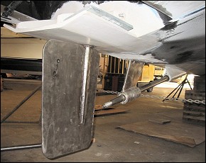
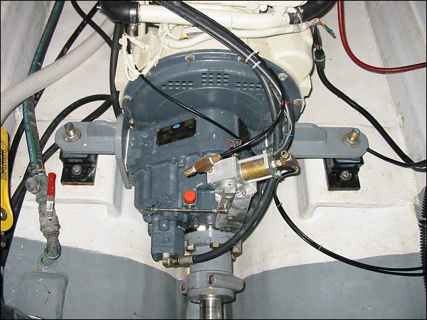
Since we know that the engine/transmission is always moved into final alignment to the shaft and we are now very sure that the transmission is within about 1/16″ from it final position, we now design and build our rear supports/transmission brackets and get them installed. Every installation is different and one must be “open minded” when designing mounts and brackets to make the best fit/best design for each vessel.
I just about NEVER want the isolators to end up on top on the stringers. We like them inside, outside, on small pedestals, or on some type of bracketing that allows thru bolting of the isolator to a metal bracket. Since just about every stringer is not straight, parallel to the finished centerline of the engine crankshaft, not even in thickness, etc., we design our bracketing in such a way to allowing floating them in place on a epoxy bed in perfect alignment before bolting in place. Once we have designed and fabricated our transmission mounts (usually consisting of 4 pieces) – port and starboard trans brackets and port and starboard stringer brackets, we can install them. With that done, we can now remove our temporary wedges, etc., and put that transmission on its own mounts allowing very easy alignment for the rest of this project.
Rudder
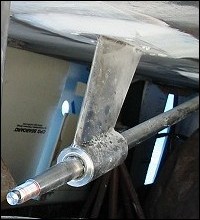
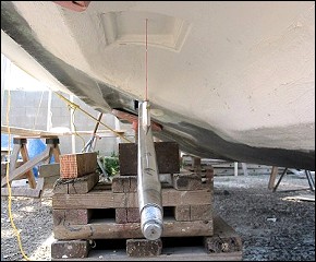
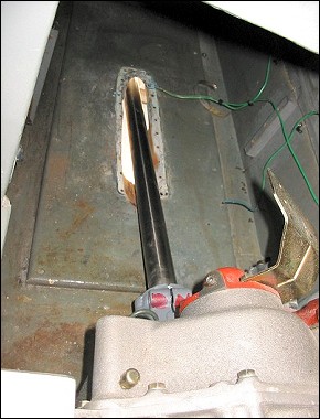
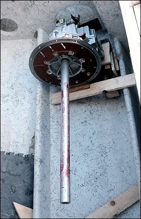
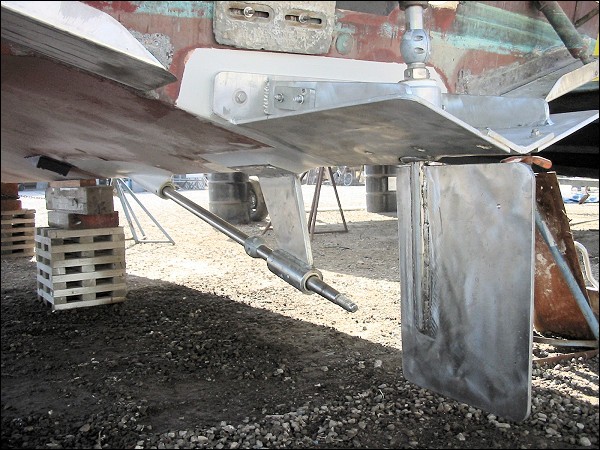
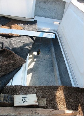
Next we will typically use a small stub shaft to locate our first cut thru the bottom. Can’t go much farther until we take that plunge.
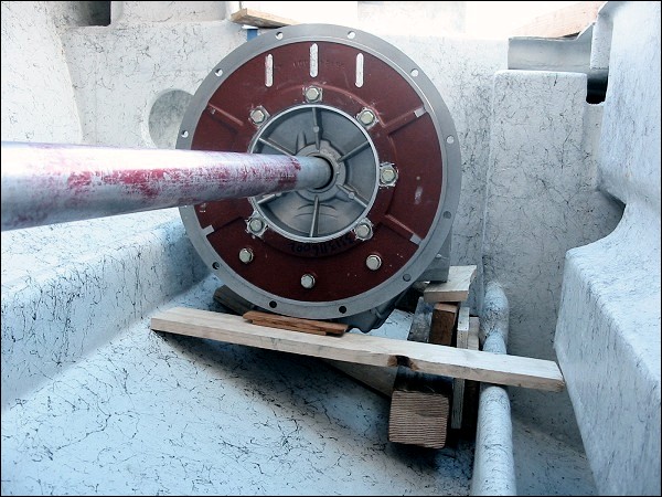
By now we know our approx. shaft length, so we install a dummy shaft, usually longer than we need. We like it to “initially” go past the rudder center, if possible, as it gives us a easier way of locating the rudder center exactly where we want it. On single engine boats, it’s always on boat center, on twins you have a choice-on center, or offset to the outside (inside?) to allow easier shaft removal.
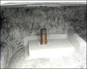
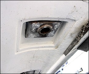
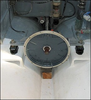
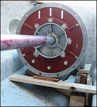
We’ve now drilled a hole and located our rudder centers. Our next step is to install the rudder log / lower bearing, permanently. Remember I said, install both ends and then fill in the center. Well this is our aft end and we really cannot go farther until we have the 100% FIXED point at least on one end. The engine/trans could still be moved some, if needed.
Because of all of the imperfections in boat hulls, we always float our metal pieces in place with structural epoxies suited for the purpose. After curing, exactly in the correct place/alignment, we then drill/bolt/add backing plates/caulk as needed. It’s now 100%, and we have our first fixed point on the vessel that will guide us to the rest.