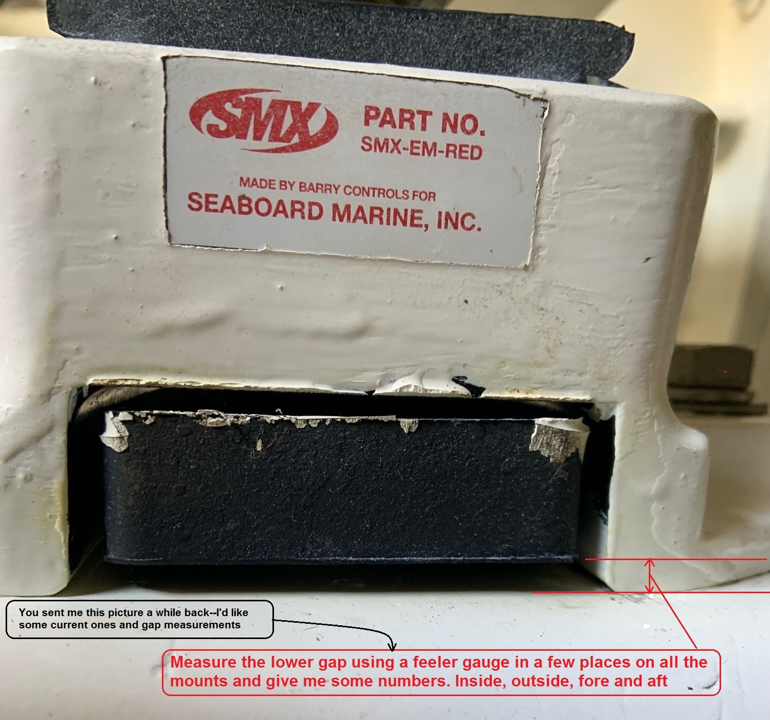
On cast housing isolators with a concealed snubber, a feeler gage can be inserted through the half-moon opening under the base casting to get an approximate measurement of the gap. If the gap is 8 mm (0.312 in) or more, the isolator is under-loaded. If the gap is less than 1mm (.040in), the isolator is overloaded (see Figure 4-16).
On pin-style isolators, the pin serves as a load indicator. The isolator is correctly loaded when the pin is at least 3 mm (0.125 in) from the edge of the hole in the cast housing. If the pin is touching the top of the hole, the mount is under loaded and will not isolate well. If the pin is at the bottom, the mount is overloaded (see Figure 4-16).
- To apply load to an isolator, turn the adjusting nut so that it moves upward. This lifts the engine at that corner, increases load, and compresses the isolator. You will see that when the nut goes up, the snubber goes down. To reduce load, turn the adjusting nut so that it moves downward. This lowers the engine at that corner and relieves load on the isolator. When the nut goes down, the snubber goes up. Adjust the isolator loads until the front isolators have similar snubber gaps and the rear isolators have similar snubber gaps.
- Rotate the isolator housing, if necessary, to align its horizontal centerline parallel with the crankshaft centerline (see Figure 4-13). The yaw angle must not exceed 2 degrees. Tighten the isolators down to the stringers.
- Adjusting the isolator snubber gaps may change the shaft flange alignment. Recheck alignment and repeat the process as necessary, to make sure that the isolators are properly loaded and the engine is aligned with the shaft. If major adjustments are needed to achieve proper loading and alignment, it may be necessary to add shims or modify the stringers to center the isolator studs to the engine mount. The vibration isolator top nut must not be more than 2 mm (.080in) above the flat on the stud. If the nut is too high on the stud, shims should be added under the vibration isolator to raise it.
- Finally, the isolator stud lower nuts and upper nut must be tightened. Torque values are given below (see Table 4-2). Hold the adjusting nut and tighten the jam nut, then hold the stud with the flats or hex socket on the top of the stud (to prevent twisting) and tighten the top nut.
| Adjusting Nut / Jam Nut | Top Nut | |
| .75 inch Diameter Stud | 129 N•m (95 lb-ft) | 195 N•m (144 lb-ft) |
| 181 N•m (134 lb-ft) | 285 N•m (210 lb-ft) |
Table 4-2: Vibration Isolator Torque Values
- The vibration isolators may settle slightly after installation. Re-check the engine/shaft alignment and snubber spacing after several days under full engine weight load. Minimum snubber gap is 1 mm (0.040 in) after 7-10
days.
NOTE: The final alignment should not be done until after the vessel is waterborne and has been loaded to its
normal operating condition for at least 24 hours. The alignment should be redone each time a flexible
mounting system is disconnected from the propeller shaft.