
Description
For the past 15 years I’ve been thinking about (and trying to understand) the crankcase breathing system on the Cummins B Series engine in typical marine applications. I wanted to develop a simple and cost effective CCV system for this much desired engine. View EnviroVent Kits & Pricing This period of “contemplation” goes back years ago and sprang to life during a plane ride with my Cummins distributor/sales rep, Mike Hoffman. It was the only time I ever flew in “First Class” and after a few bottles of red wine, we coined a name: “ENVIROVENT.” Now I feel that I have something to offer; a simple and effective CCV system that will make most everyone happy. But first I’d like to give some history and some basics for understanding the crankcase venting system that is used on this particular engine, along with the ABC’s of what a CCV (CLOSED CRANKCASE VENTILATION) system is supposed to accomplish.
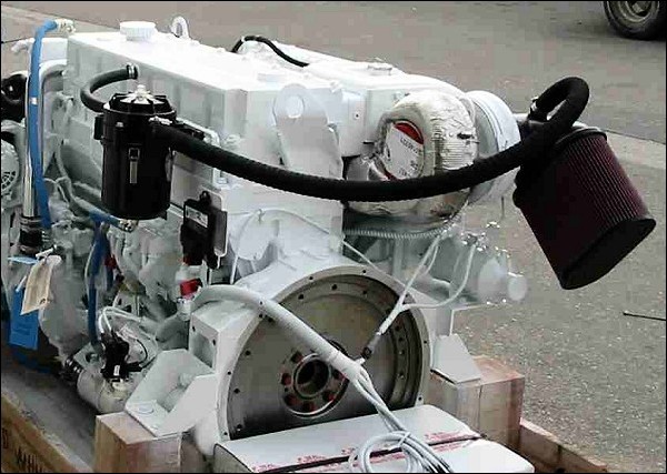
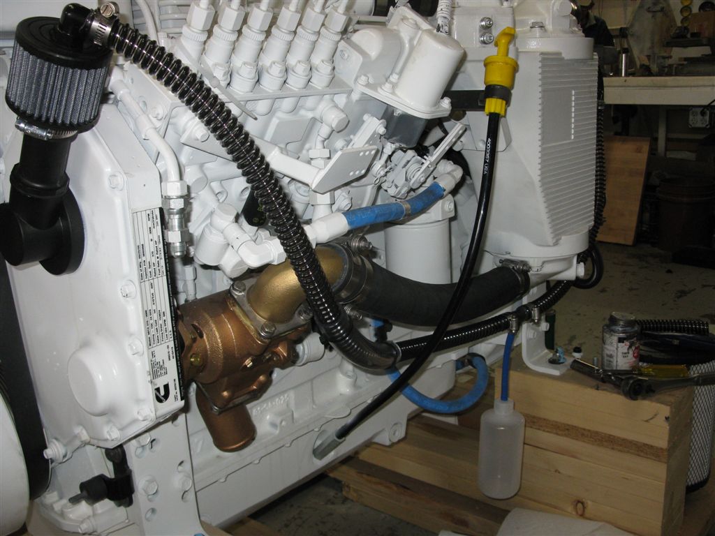
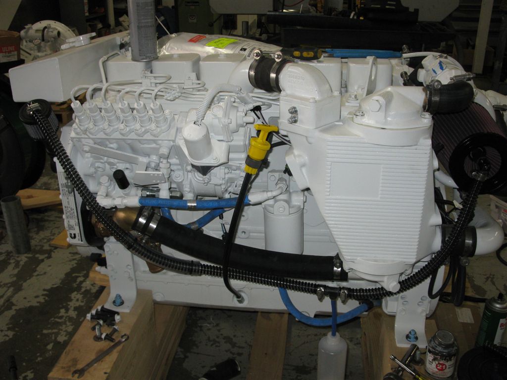
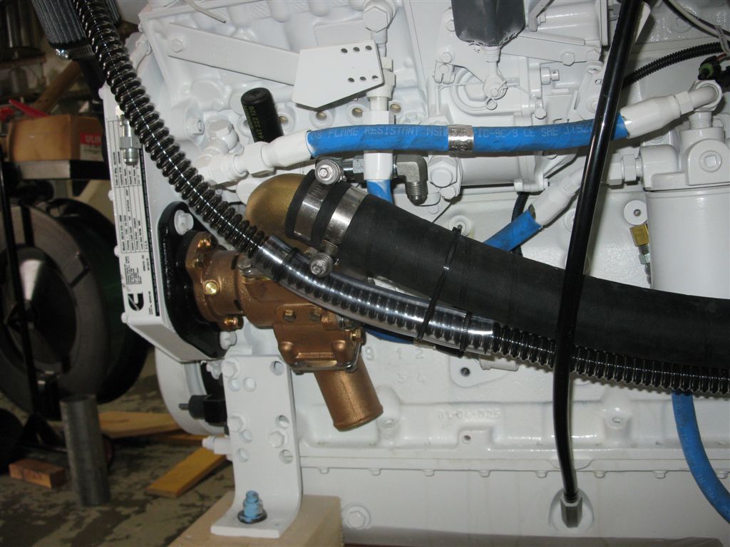
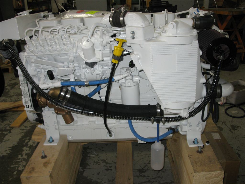
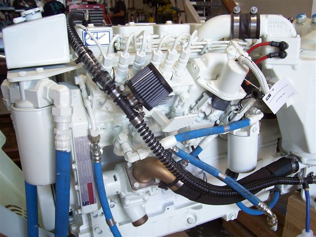
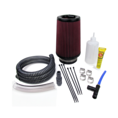
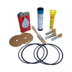
EnviroVent Kit for a Cummins 6BTA 5.9
Since first introduced to marine service in 1985, the Cummins 5.9 liter “B Series” has become the most popular, well respected, and most sought after marine diesel in this size range ever produced, and this status is well deserved. Around late 1988 or early 1989, the engineers at Cummins released the 6BTA 300 B version (CL 970) and along with this new high performance rating, they also introduced a low profile, flat cast aluminum oil pan. Somehow, during the design of the new oil pan, the design team assigned to this new oil pan project missed a very important engineering design feature that should be part of any oil pan design… The pan was so shallow (about 9″ lower than the center of the crankshaft), that under normal operating conditions the connecting rods would “dip” the oil. Not good and goes against all of the published literature I have ever read INCLUDING Cummins’ own oil pan design requirements. As time passed, and the RPM range of the B grew (3000+ with the 1997 release of the 370 Diamond) the rod “dipping” now became more like rod oil whipping. Instead of deepening the pan an inch or two, the engineers designed a new baffle system to help contain / control oil sloshing in the oil pan… Strictly a band-aid approach IMO, although it did help some. I think the most prevalent application part of the overall design approach Cummins chose was that the engineers DID NOT understand typical marine vessel operation (planing vessels for sure) in that under normal operation, the nose of the engine rises substantially and the oil in the shallow flat pan flows to the back of the pan and rises causing even more turbulence and oil whipping leading to higher than normal crankcase vent pressure.
Now comes the other part of the equation and that is, how to control this excessive oil whipping and to mitigate the typical issues (aerated oil, extra heat, pressure and possibly even a HP loss) that accompanies this. The standard location of the crankcase vent is the left REAR side of the engine (side tappet cover) and/or behind the aftercooler (SWAC 6BTA’s). This was a fine location for the Dodge trucks and all the industrial applications (they had 12+” deep oil pans), but for the typical marine application, this particular placement of the vent exaggerated an already touchy issue. With the oil backed up against the rear of the oil pan, with the connecting rods whipping the oil, with continuous higher RPM’s than you would see in non-marine applications, with the flat shallow oil pan coupled with a nose/front up attitude (2-15+ degrees) of the engine during normal typical operation, what you ended up with was oil being pushed out of the breather in varying amounts. Sometimes a few drops over a course of a day’s fishing, and sometimes enough to lead an operator to think he had problems with the engine as “blow-by” at times would seem excessive. What also would happen with this shallow pan, was that oil level was hard to measure accurately because there was only about 1/2″ between the amount for low (13 QT mark on the dip stick) and high (15 qts). Between this difficult-to-measure amount of oil in the pan and the natural tendency of an operator to keep the oil at the high mark (or think that “more” has got to be better than less when it comes to oil) all worked together to further exaggerate the problem of oil mist being pushed unnecessarily out of the crankcase breather or “draft” tube, as it is called in automobiles.
Over the ensuing years between 1997 and 2004, the engineers at Cummins tried many different methods to help contain the oil in the engine. First were baffling changes and new dipstick designs for the pan itself, and next they followed with new engines being shipped with a small plastic bottle attached to the breather tube (short lived). After that, we received engines with the rear side vent attached to a new front timing cover breather that had a “T” and a draft tube going down and tucked behind the injection pump and seawater pump. This was probably their best effort, although the installation or maintenance of this design was impossible to deal with as one could not realistically reach the tightly tucked-in hoses or clamps making up the device. Along with this, they also changed the orientation of the side cover tube from pointing DOWN to UP… Basically I lost track of the different methods and parts used to accomplish such a seemingly simple task – Having a simple crankcase ventilation system.
This is what we have learned thru all of this over the years.
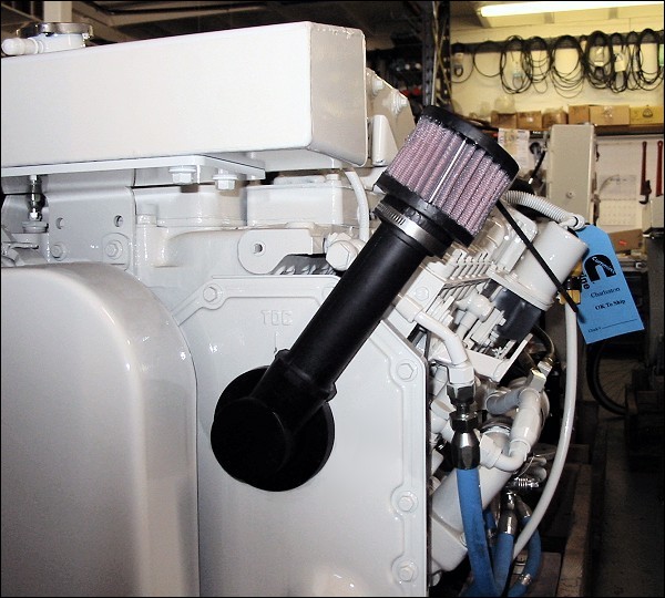
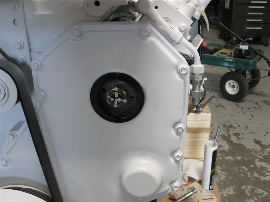
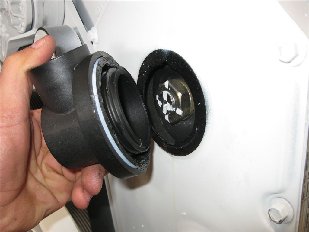
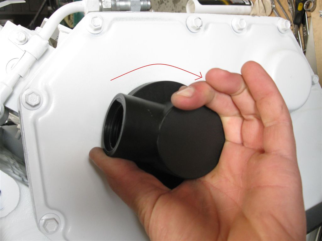
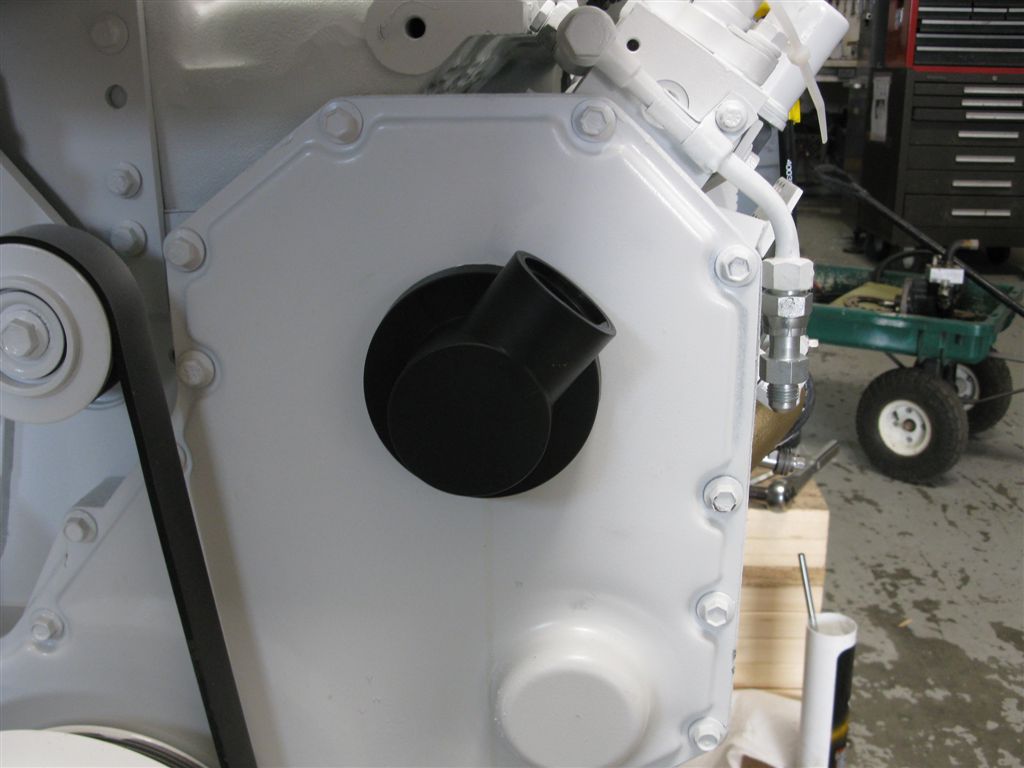
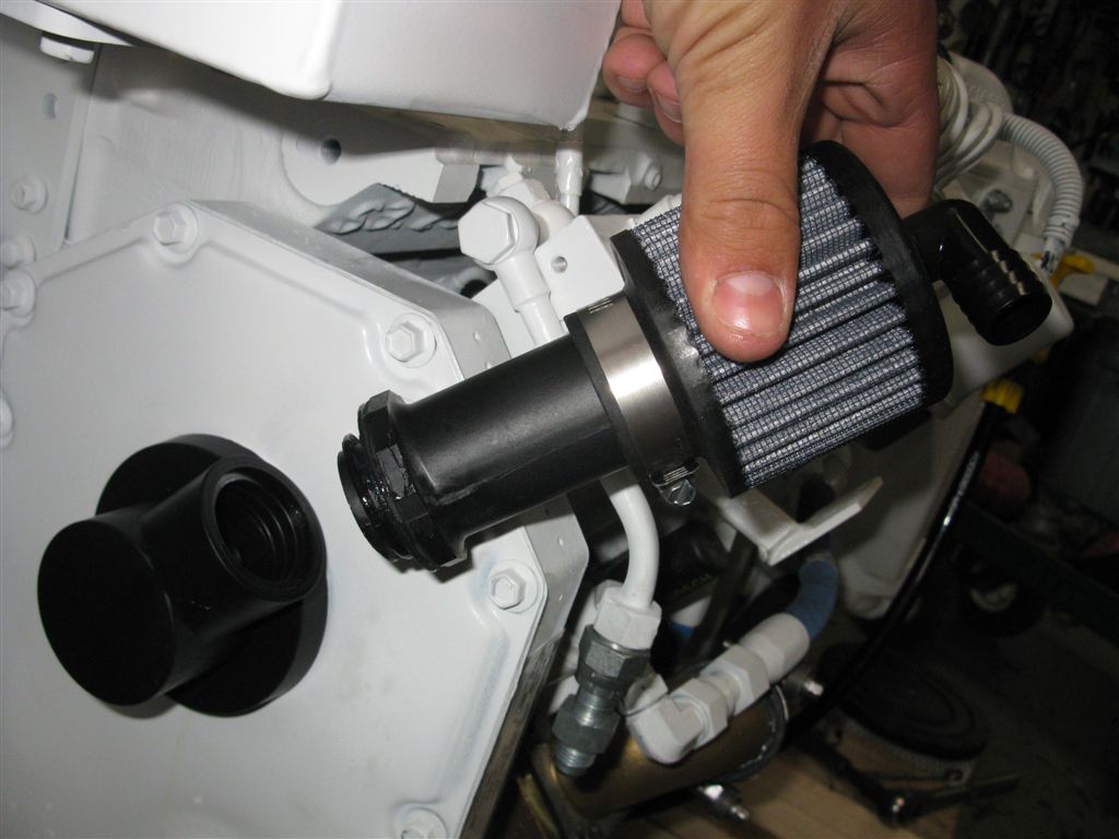
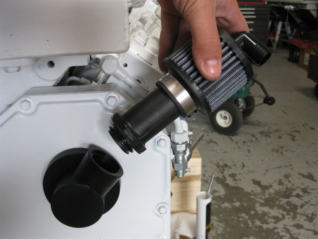
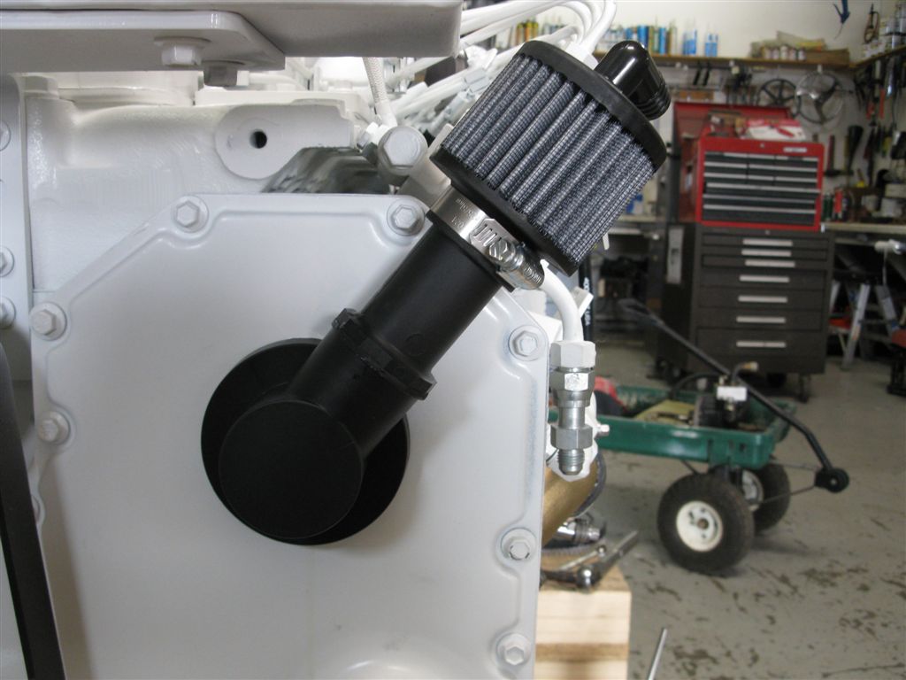
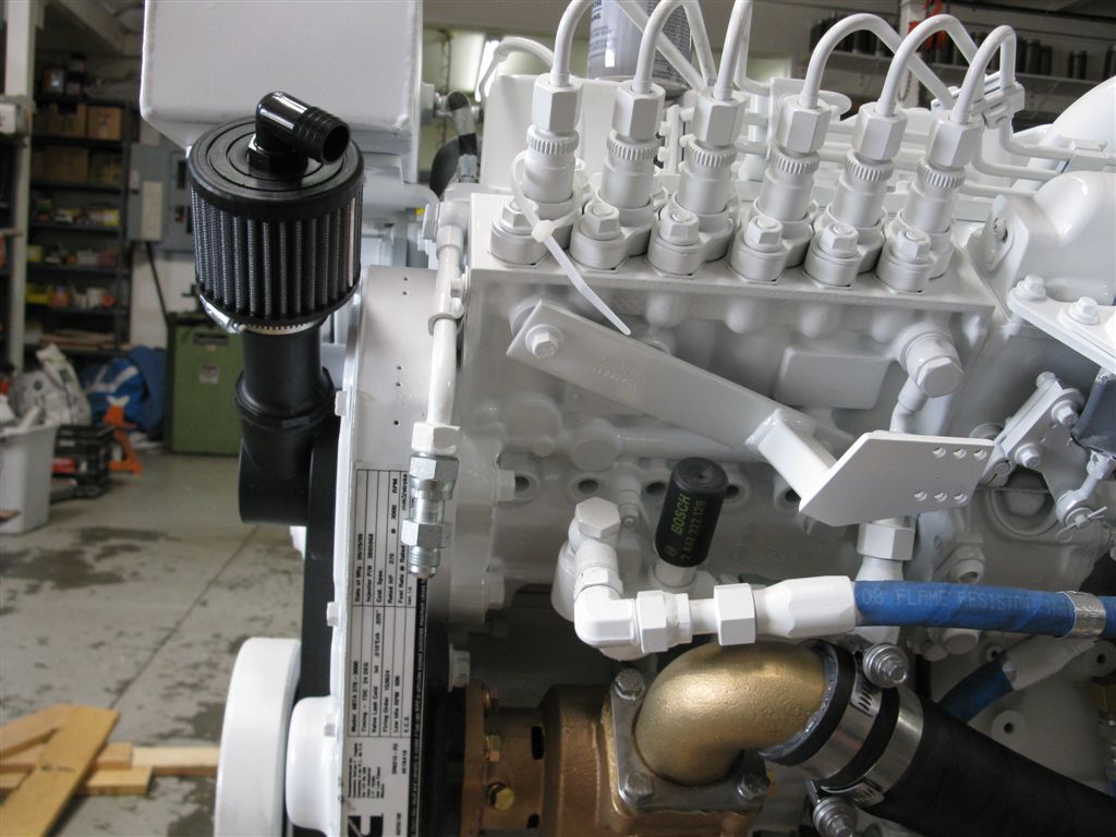
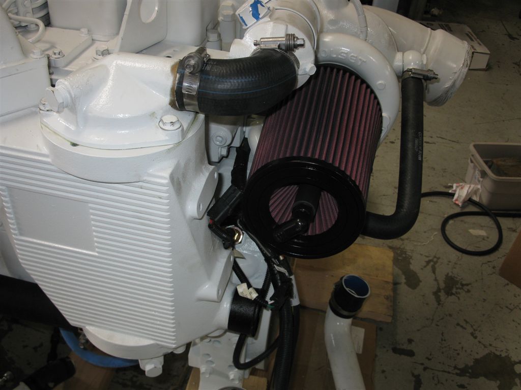
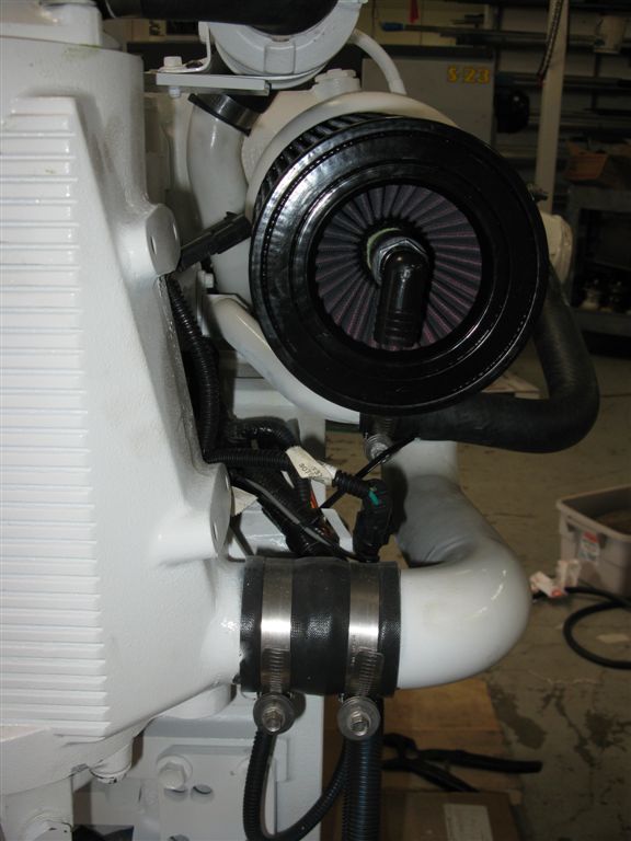
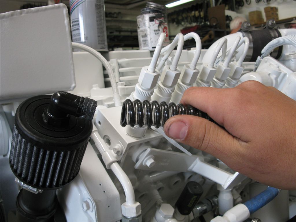
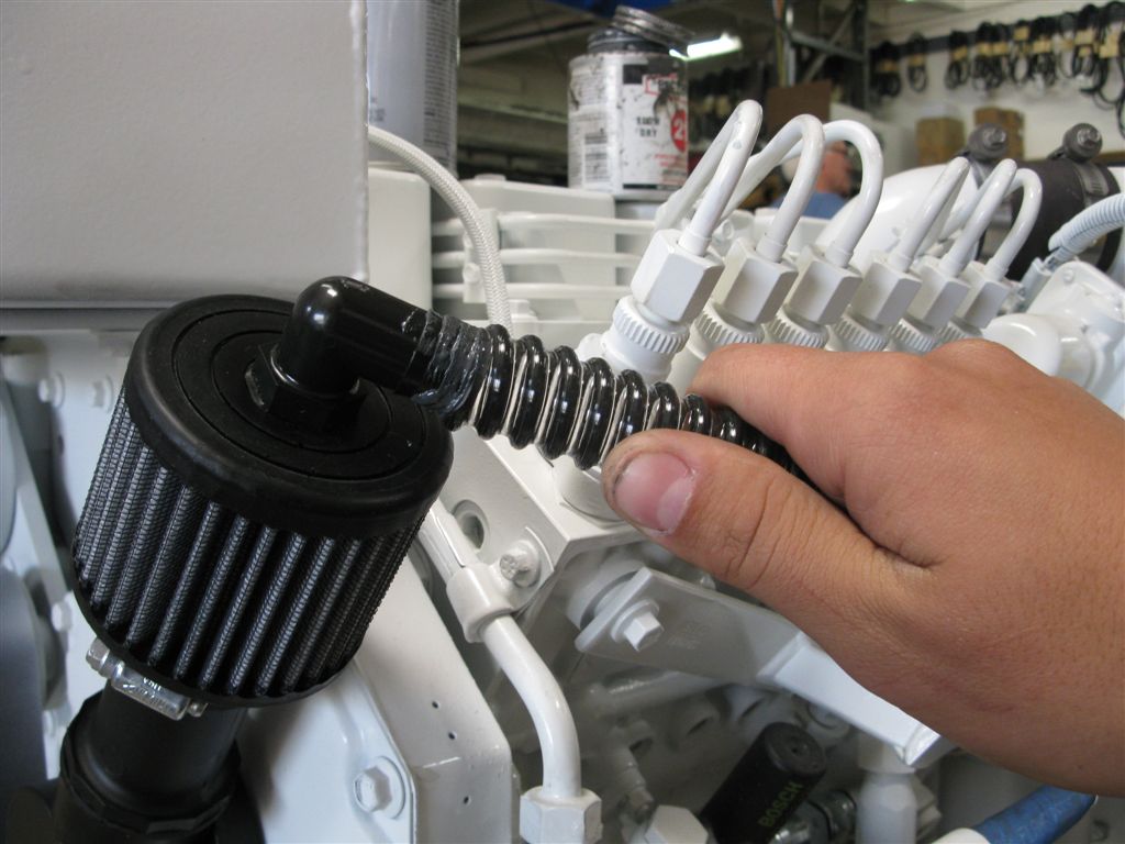
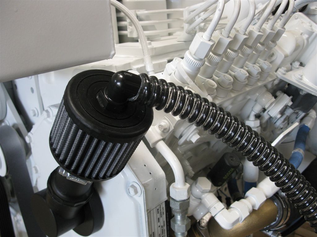
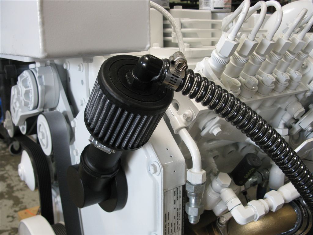
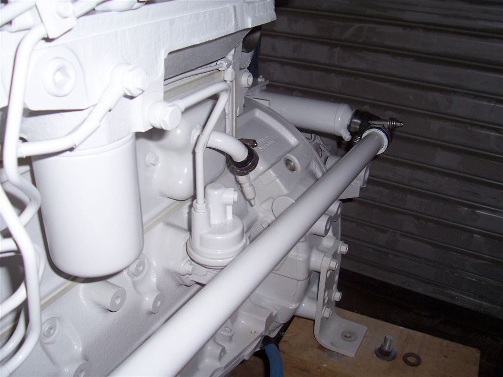
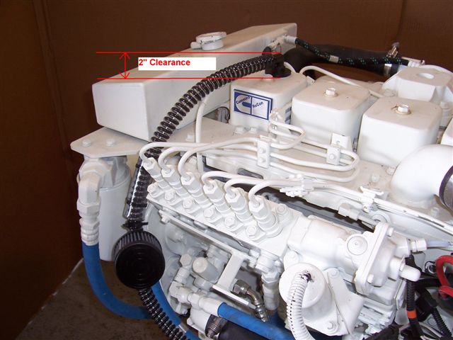
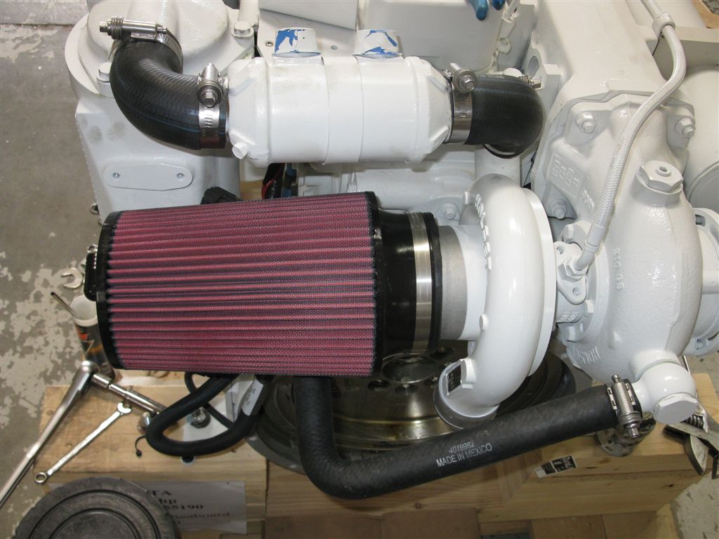
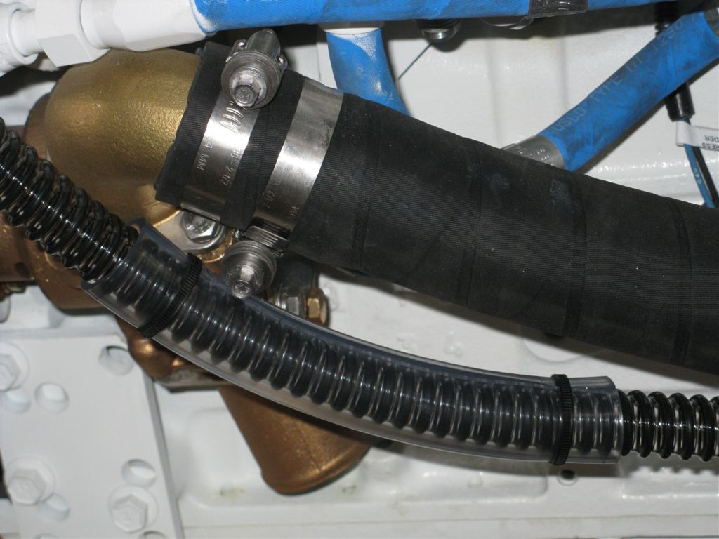
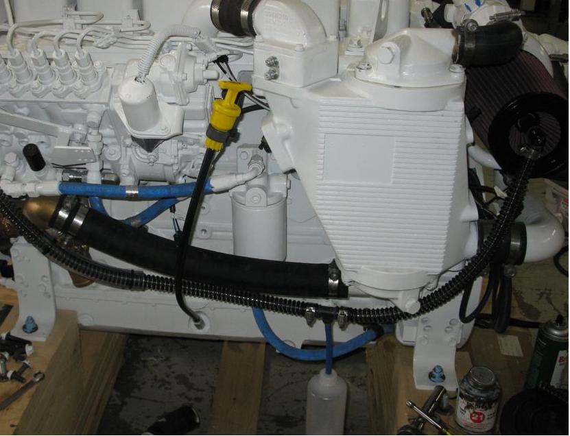
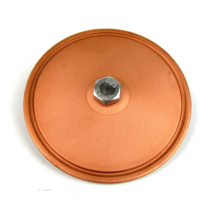
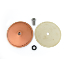
For all inline or conventional drivetrains with the engine facing the bow of the vessel, the Cummins B series engines like to breathe from the front timing cover. Reason?–It is because it’s a very “calm place” inside the engine and the timing case, due to its base design, has a tendency to condense much of the oil vapor and return it to the pan (due to that slight cooling effect and large surface area of the steel cover). With this knowledge we went about designing a simple and effective way to allow the engine to breathe from this area. We adapted some already made Cummins’ parts to allow the installation of a special S&B crankcase type air filter (known as a PCV vent filter in the automobile industry). Our first and still used design was really simple. We capped off the rear side vent tube, installed this front timing case vent and now had a super simple solution to the problem of a “dripping vent tube”. Too simple but very effective. As an added plus for this system, simple oil filling from this location is now easy when overhead clearance is minimum.
But like any crankcase engine vent, even the slightest amount of crankcase fumes that are released can be objectionable in many installations. Cummins knew this too, and along with the market’s demands for having a super clean and decent smelling engine room, Cummins started offering the well proven and highly regarded Walker AirSep as an option for the “DIAMOND” Series of mid-range engines (B and C series) that were released around 1997. I believe Walker Airsep ( an air cleaner and oil/fume separator in one) was the first CCV system used in marine service that was widely accepted and proved to be a godsend to 100’s of Detroit 2-stroke owners where the Airsep proved its worth in reducing oil leaks and oil mist in small “boat type” engine rooms. Other companies also saw a demand for a “closed type” crankcase ventilation system – and before long, the “CCV”, as they are known, were made in different designs and being marketed by companies such as Racor. Along with the market demands for a CCV product, the EPA was closing in with new emission standards that would effectively require a CCV system on all internal combustion engines. The push was on!!
As to understanding what a CCV (Closed Crankcase Ventilation) is and how it works is quite simple. In its simplest of forms, a CCV system is merely a mechanism that enables the normal crankcase fumes to vent thru a hose to a “low pressure area” (a tube from the engine’s air intake-the “low pressure area”) and allow the “fumes” to be burned during combustion, while separating most of the liquids. In actuality, I am not sure why this is called “closed” (IMO, it’s not really closed in the normal sense, like a closed “bottle” or refrigerator), but it makes the venting “out of sight and out of mind”, so that must be the definition of “closed” in this case. Yanmar and some others use a very basic system by putting the crankcase breather hose near the air inlet and accomplish this “low pressure” thing, although this does not meet the meaning of a “closed system”, but can act in a similar fashion under some conditions.
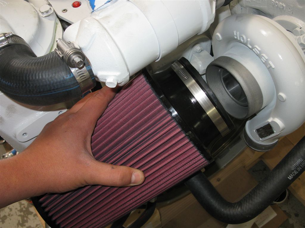
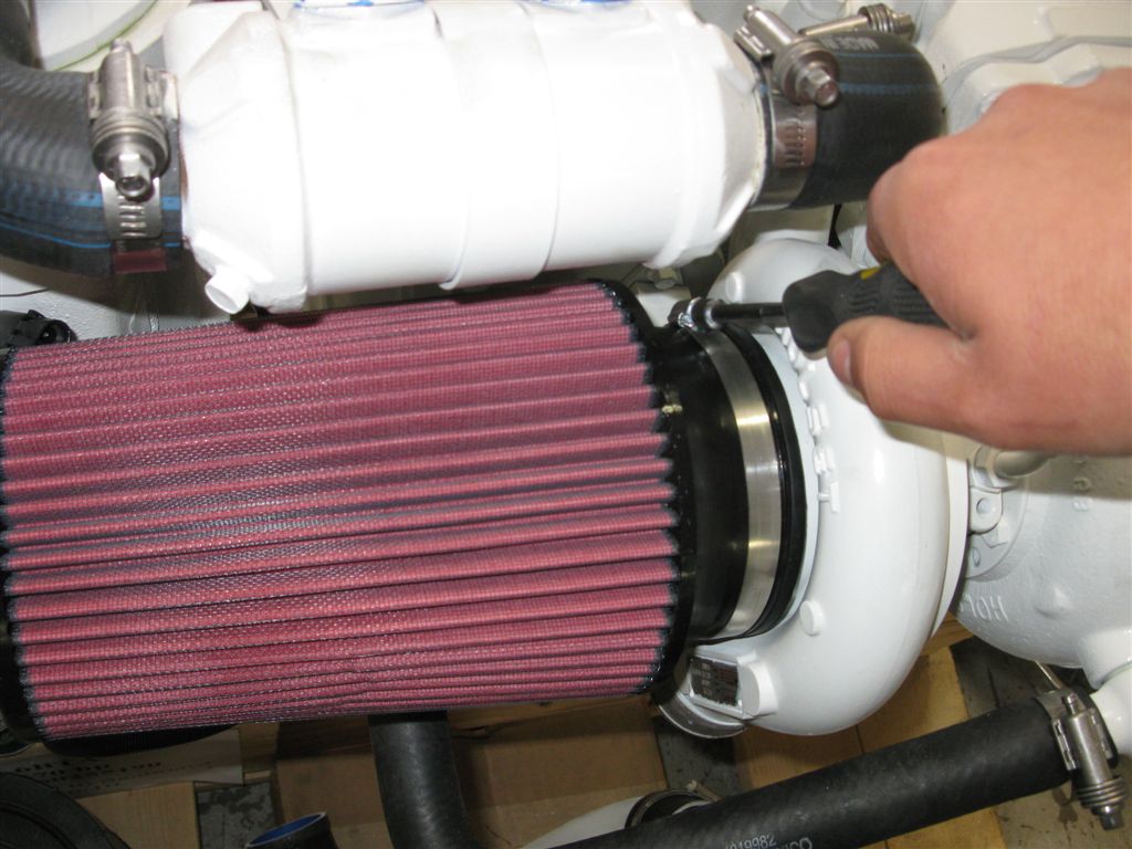
Although the Walker system worked extremely well for 2-Stroke Detroit owners and possibly other makes of engines, this was not always the case when installed on a Cummins “B” series engine. The base design of the “B” and its own inherent crankcase venting problems have a few conflicting issues that prevents the Walker system from performing as intended in many instances. This really is not because of a problem with the design of the Airsep (it’s quite clever and works well in many applications) but rather, the way it must be installed on the Cummins B.
By design, the accumulated or condensed liquids in the Walker Airsep drain out the bottom of the installed unit thru a tube connected to the engine oil pan (because of a drain tube check valve.) This valve should ONLY open when the engine is not running – (normal crankcase pressure during operation keeps it closed). Well, again we have overlooked a flaw in the system in that these liquids, in many cases, are asked to drain thru this drain tube that can be level, or even “uphill” in many installations. Since “gravity” is needed for draining to occur (along with a working one-way check valve that is supposed to open from the WEIGHT of the liquid accumulation above it), one can see that this might not occur in many installations or under certain circumstances. The air inlet of the turbo is quite low and aft in relation to the oil pan of the “B” (that’s where these liquids are supposed to drain). Couple that with any nose up attitude of the engine, and if one looks at a standard Airsep installation on the “B”, it is easy to see why problems with draining these liquids could and do occur. The other base flaw and potentially more troublesome in the adaptation of the Airsep to the “B”, is the routing of the gases AND liquids to the Airsep itself. In most all installations, the vent tube hose goes down first and then turns UP, forming an upside down loop or “sink trap.” What happens in as many times as not, is that the drip by drip oil expulsion of the venting system on the “B” fills this sink trap to where the crankcase is now closed, and effectively, one of two things can happen depending upon the operation and condition of the engine when this occurs. The pressure from the crankcase coupled with the suction or low pressure area from the Airsep itself, slugs a bunch of liquid into the collection chamber of the Airsep-In simple terms, the system cannot deal with it and the liquids are now sucked thru the turbo. This leads to premature turbo fouling and worse, aftercooler fin contamination and clogging. A second result of this crankcase vent hose sink trap is that as the pressure builds to excessive levels, the gasket underneath the side tappet cover blows out resulting in quite a mess. Other issues that we have seen over the years w/ the “B” and the Walker Airsep adaptation, are stuck one-way drain valves. We have found them stuck in the open position causing oil to pump up into the Airsep and then into the engine, and also stuck closed leading to oil accumulation inside the Airsep and then being sucked into the engine. To eliminate this potential problem, we would suggest yearly (or more often) inspection, maintenance / replacement of this valve to insure proper operation. It’s usually located at the bottom of the drain tube just before the connection of it to the oil pan.
This leads us to another issue that we believe is something to consider for any type of CCV system. The liquids that accumulate in any type of CCV are typically composed of oil mist, condensed water vapor, and condensed blow-by combustion chamber gases. The gases, along with water vapor, are parts of any engine’s normal operation and contain small amounts of acids and other combustion by-products. As the engine wears w/either normal use, or thru lack of proper maintenance, installation issues and proper operation, these combustion by-products increase dramatically in amount and now are looked at as excessive “blow-by”. We now have more of these “liquids” to deal with, and IMO, I would NEVER want to return this highly contaminated “liquid” to my engine. All one needs to do to understand why is to take a sample of it to your favorite oil analysis dealer and then wait for the results.
Another popular and well designed CCV unit is marketed by Racor. This unit is standard equipment on many new engines including the Cummins QSM some John Deere and Caterpillar models. Unlike the Walker Airsep system, the Racor CCV is a “stand alone” unit and needs to be connected to a separate air cleaner to have the “low pressure” needed to evacuate the gasses. The unit, as designed, separates liquids thru an internal filter and drains them back to the engine oil pan. We like this unit as it does a very good job as a CCV system, but in all installs, we remove the drain hose connected to the oil pan and collect them manually as needed, and then dispose of them. Simple modification and, in normal engine operation, this typically only needs to be done every 50 hours or so. As to long term high hour use, the unit does require a filter replacement (I believe Racor recommends every 100 hours) and periodic cleaning inside. Although not recommended by Racor, based upon our long term experience with the unit, we believe that it works better AND requires less maintenance when hooked up in REVERSE flow… Again, this is IMO, and is from years of field trials and experience and not in the laboratory or on the test bench.
Now that we know something about crankcase ventilation and CCV’s, listed next are the favorable design characteristics of what we feel would be “perfect” CCV system.
In an ideal world, it would be nice to not let the engine ingest anything but the cleanest possible air. But, this is not the case nor will it ever be, at least in the marine environment. Marine engines must operate in the confines of a small engine room where just the engines need for combustion air at cruise speeds will typically cause an air change in the engine room 1-3 times per minute. Just figure it out – IF you are using 400 “cruise HP” (about 20 GPH) to move your vessel at 24K’s, air consumption is about (or over) 800CFM…. Every diesel engine has varying degrees of “blow-by”, and without some type of CCV, where do you think this blow-by ends up? All around your engine room (some condenses on the colder surfaces of the engine and engine room, but most of it goes into the air cleaners. The less ventilation you have, more will find its way back quickly to your air cleaners. In just about any engine room, when you look at the back of an alternator, you’ll see signs of blow-by condensing on the back surfaces or on some of the internal heat-sinks. The fan on the alternator sucks in ambient engine room air, and most any vapors in your engine room will condense there. If you have nothing there, then you have an exceptionally clean running engine and great ventilation besides, or you have a good CCV that is working well.
A few features that make a good CCV system:
- A good CCV will limit the amount of vacuum on the system and / or be adjustable for individual applications. This is an important design function of any CCV unit and can be accomplished in many fashions. We prefer a much simpler approach than most other manufacturers of CCV units.Since our unit is “engine specific” as to sizing, the unit and connection assemblies limit the vacuum by design and actual size, and do not rely on an expensive “vacuum regulator” with springs and diaphragms that is far from “maintenance free”.
- A good CCV unit will not let liquid into the turbo or allow those ugly condensed liquids back into the engine, but will collect them as needed before they make it that far. In a nutshell, the perfect CCV would be one that could ingest all the normal (and a little extra) crankcase bypass from modern “state of the art” high speed marine diesels, separate all of the gases from the “pukey liquids” that will foul aftercoolers, turbos, etc., let the liquids be captured and drained in a convenient way to be discarded, and then burn just the captured gases / crankcase fumes, AND will not create some other high maintenance problem.
- A good CCV system will make it easy to capture and drain those liquids. You don’t want that nasty “puke” as I call it, back in the engines oil pan.
- A good CCV system is simple to understand how it works.
- A good and well designed CCV system is simple to install.
- A good CCV system is simple to maintain AND inexpensive as to long term maintenance.
- A good CCV system should have many years of field testing under the varying conditions of actual use and be designed for specific engines-I know for a fact that “one size”, or type of installation, does not fit all!!
- And lastly, a good CCV should be relatively inexpensive to upgrade from your existing “open breather”.
Our new “Envirovent” system meets what we think are the features that make a good system, plus the system is designed specifically to the “B” series mechanical engines (Cummins 4BT thru the most popular 6BTA Diamonds). Although the general design principles we have used to develop the system and share with the general public could be applied to many other engines (we do on a limited basis), we are just a small company and only focus on the engines that we deal with on a day to day basis. As a reader of this article explaining our design ideas and “politics”, we welcome you to glean our knowledge and expand on it to fit your own needs.
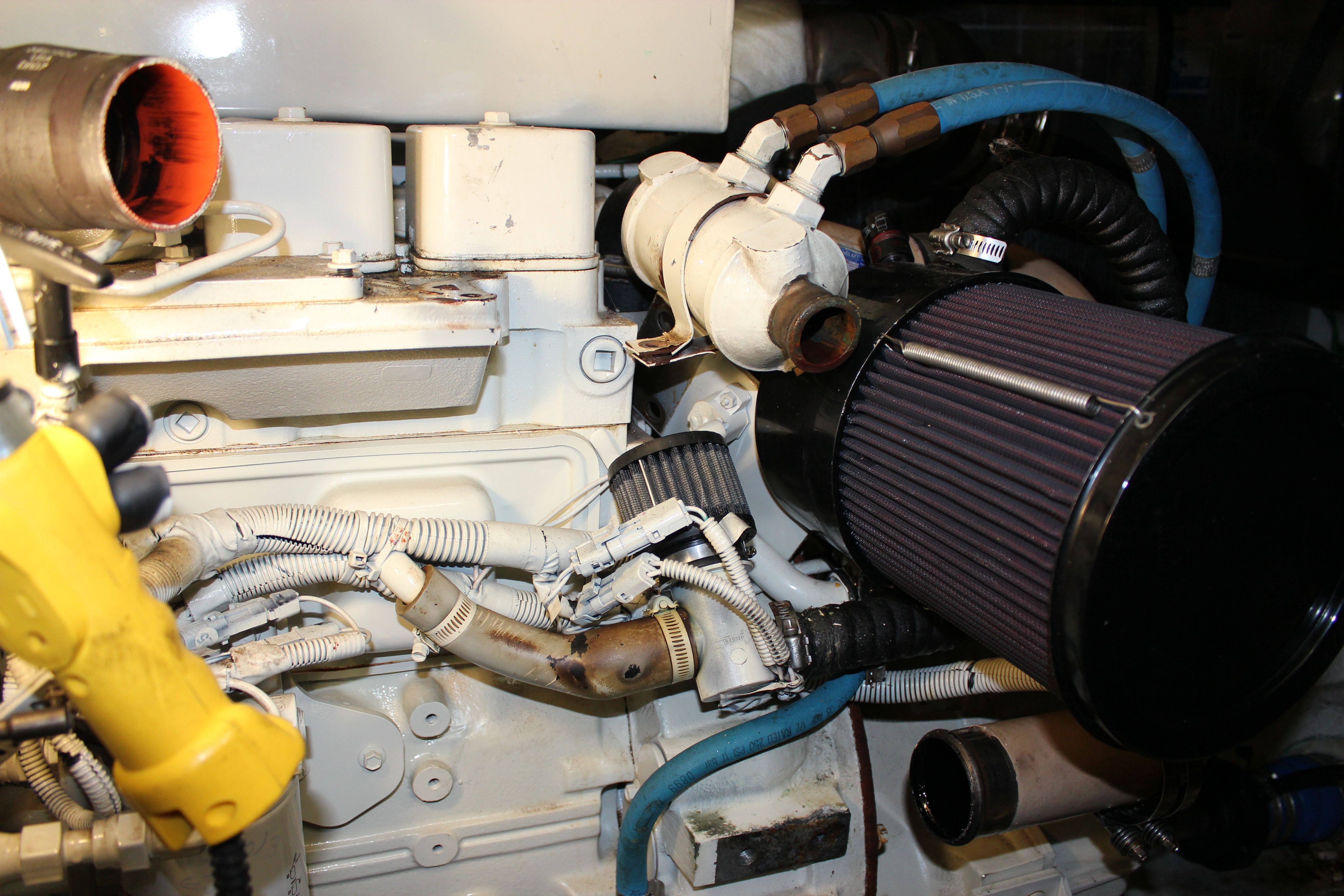
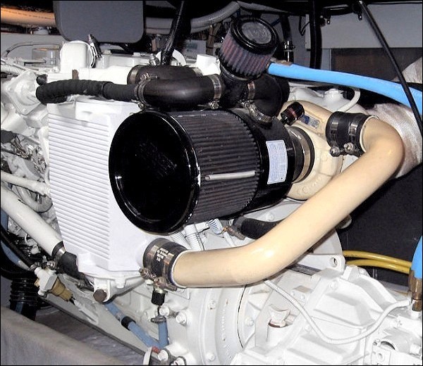
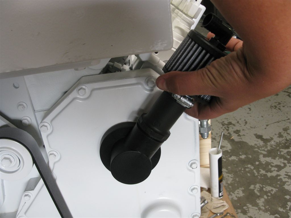
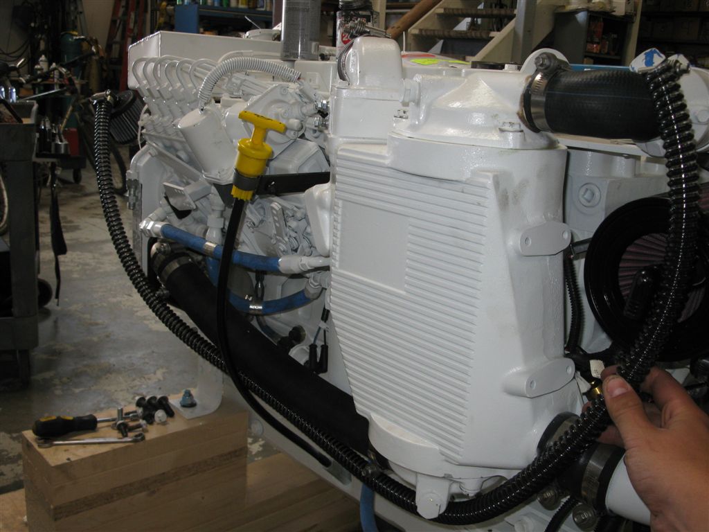
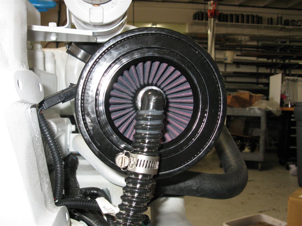
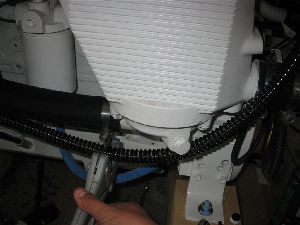
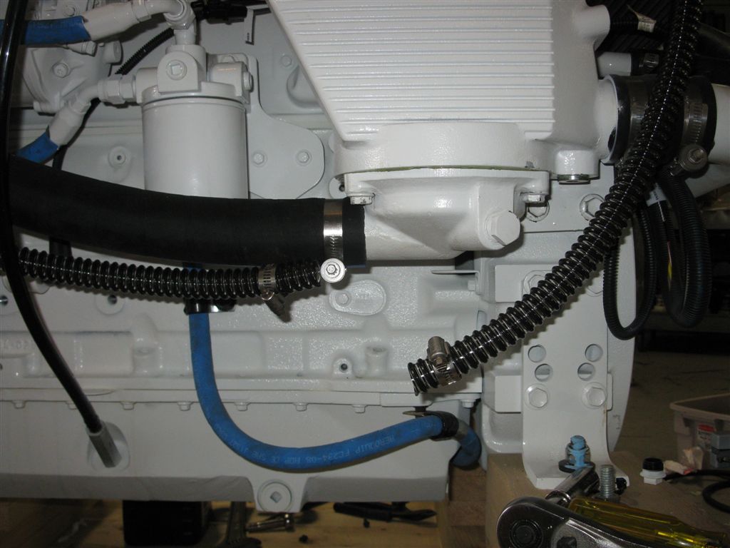
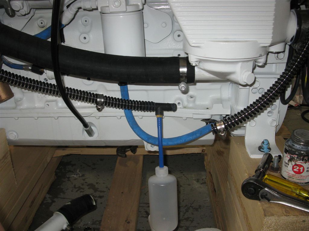
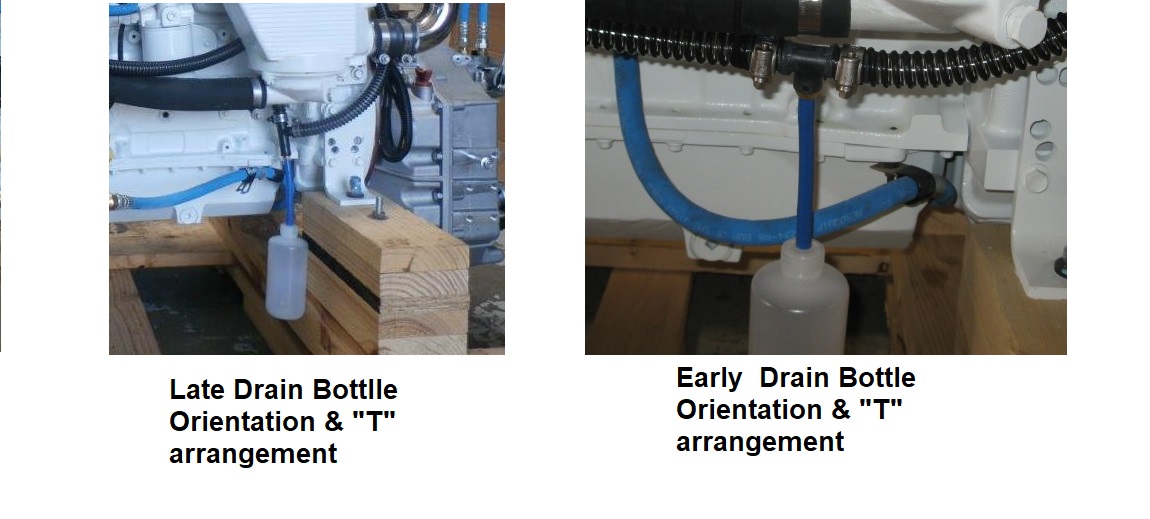
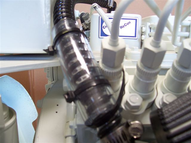
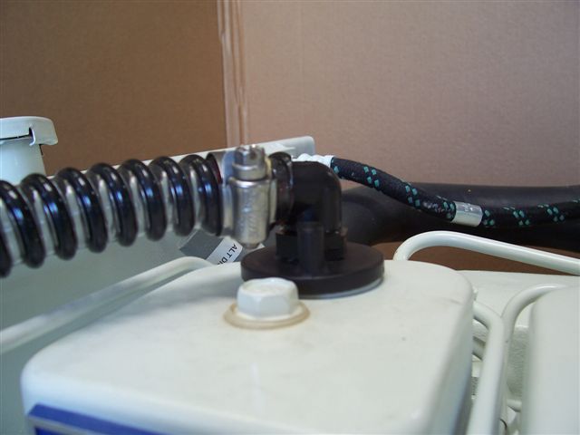
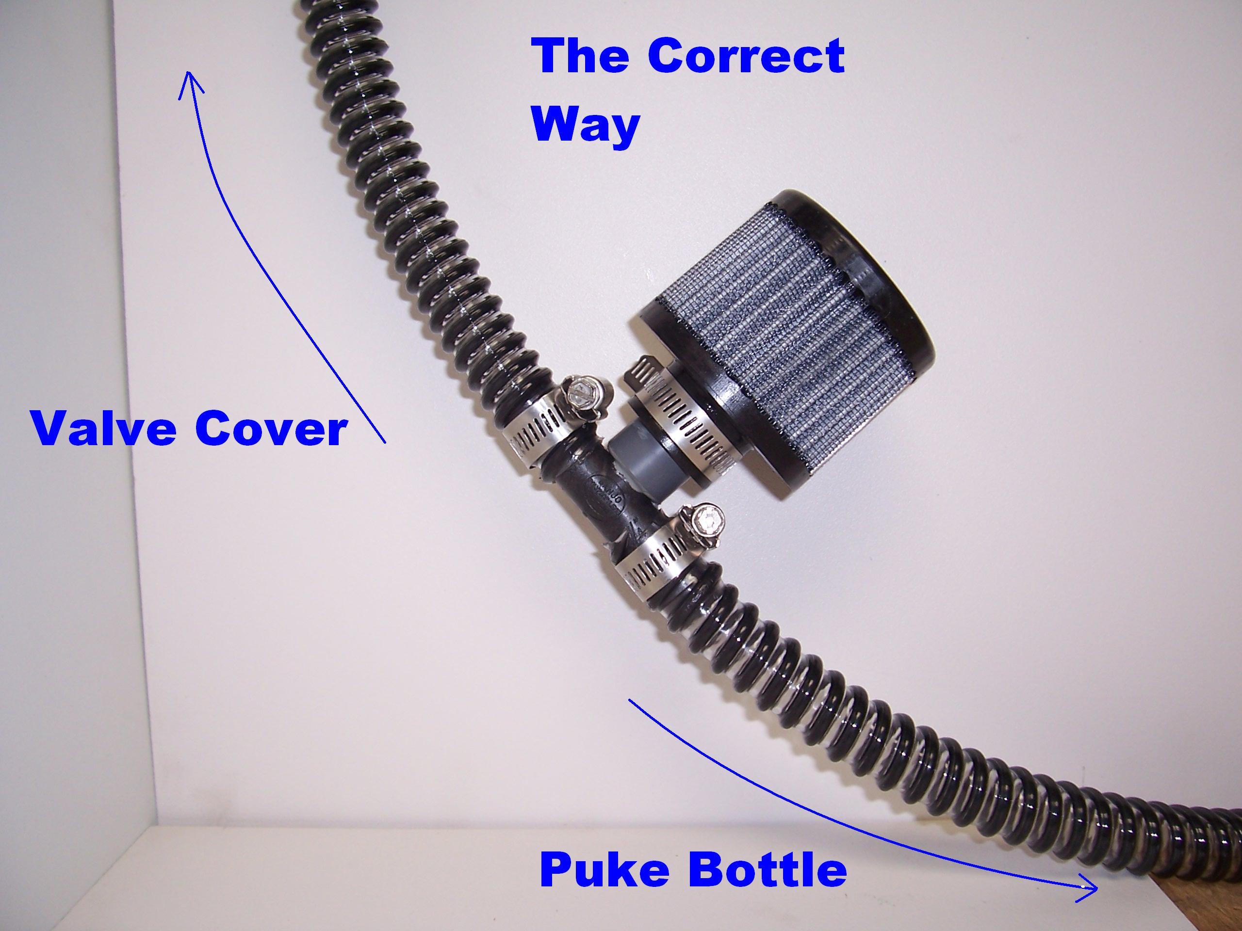
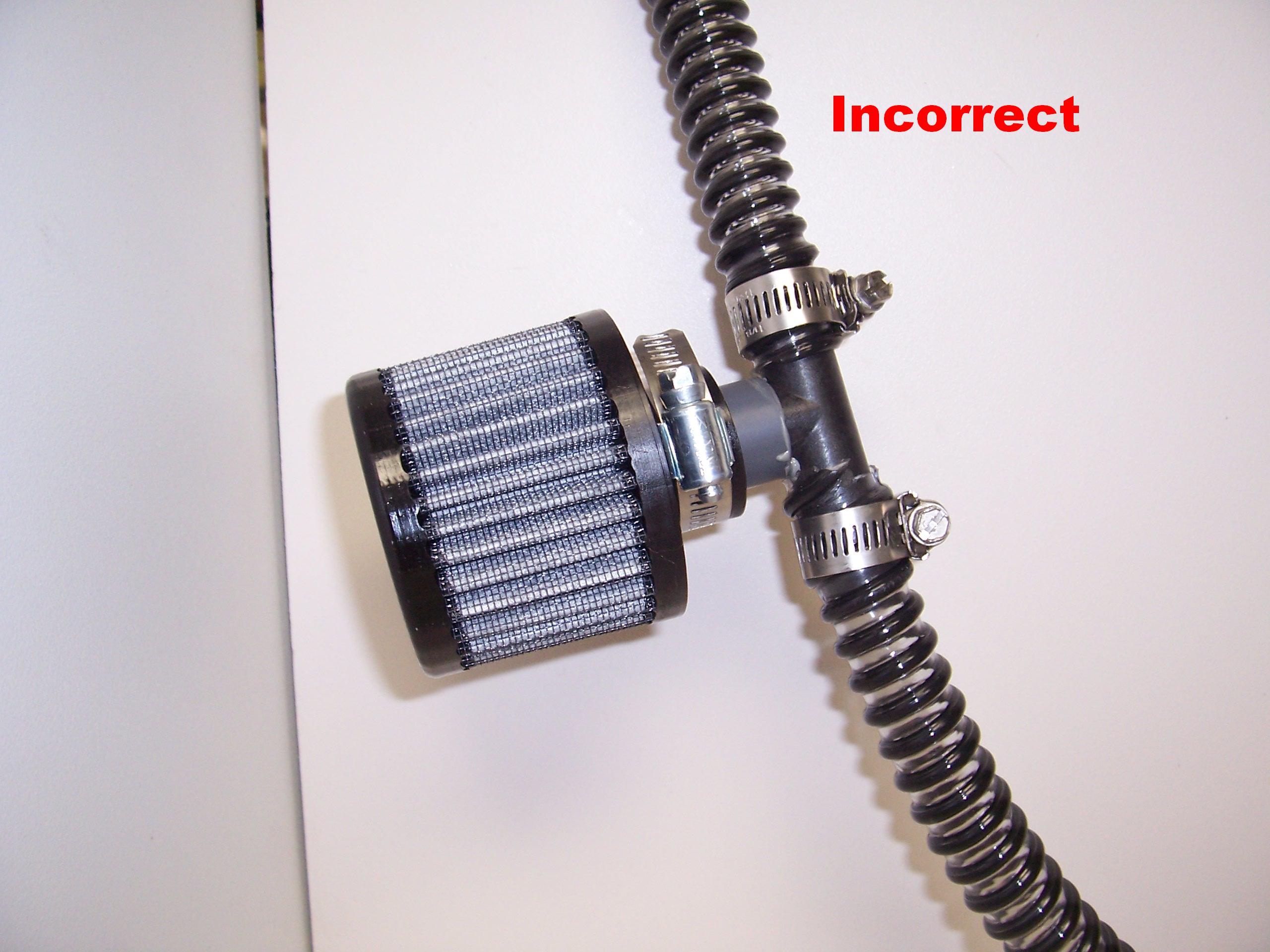
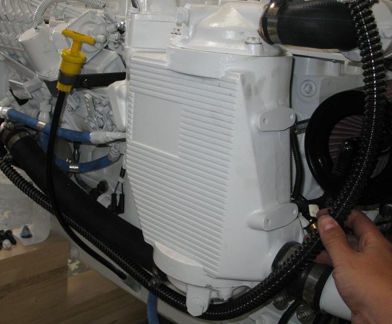
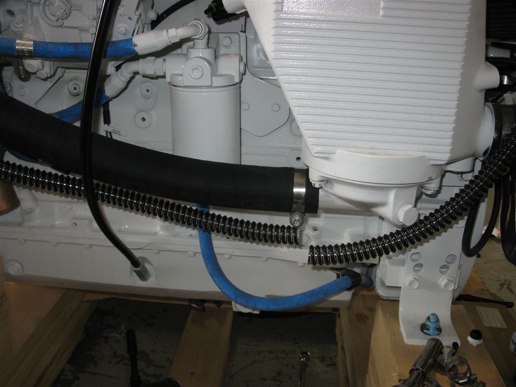
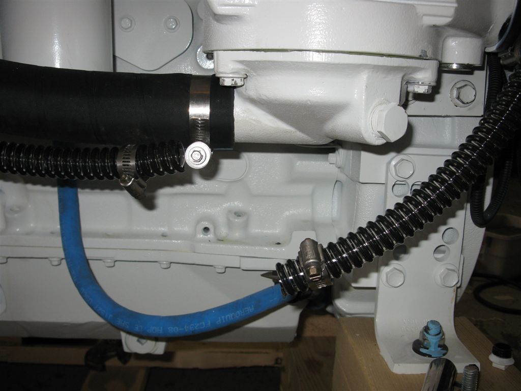
During our design phase, we had the S&B filter company put together a small PCV filter for us (you can call it our “vacuum break” limiter), and with that, our base design allowed a unique adjustable feature by tailoring the unit for engines with both normal and excessive crankcase pressure / blow-by. How? Via the way it is installed or clamped on the installation neck in relation to the “open” volume or area that is exposed to the low pressure caused by the connection to the engines air cleaner. No expensive “monkey motions” to fail or that need maintenance like diaphragm type vacuum regulators. The combination of the timing cover ventilation tube arrangement with this filter allows for a great low pressure adaptation, but “quiet spot” on the “B” Series engine for any excess oil splash to run back down into the large ID ventilation neck adapter – From there, we run a 3/4″ ID hose down along the engine side and then up to a specially adapted high performance but low restriction custom S&B filter that we use. As you can see, as the connection hose runs down along the side of the engine, it creates a natural “LOW SPOT” that will slowly accumulate any amount of “puke condensate” that may be present in a simple, but 100% effective plastic bottle. We supply a polyethylene capture bottle (about 250 ML in size) and attach it with a very high quality silicone 3/8″ ID hose. This particular silicone hose does not require any clamps or sealing compounds whatsoever because of its elastomeric properties of having an inherent soft sealing surface with 100% non-affected stretch memory. Our “T” fitting (has a standard 1/4″ NPT thread and is easy to deal with) is installed at this low spot, which is a very important design feature of this or any CCV system. Gravity is free and always present; it should be simple to understand why this natural force should be used to an advantage. Plus, because of the length of our main CCV feed hose, this by itself allows condensing of the pukey gases / liquids due to the natural cooling effect that takes place after they leave the engine. Again, no special or fancy devices needed, all of this is done with just gravity and natural cooling of the gases.
As to the type of main type of CCV connection hose one uses, that is optional-We prefer, and supply, an inexpensive, very flexible reinforced clear vinyl type hose as we like to “see” inside-Just change it out every few years when it gets funky-under 10 bucks at retail level at any marine store or Home Depot…. Just run, support, and “chafe protect” as needed. An oil resistant rubber hose may seem better for some people, but that is the installer’s choice. Note: our 15+ years of experience with “oil resistant” CCV hoses that are supplied with other systems has not really shown that they all are “oil resistant” at all.. They not only get soft, mushy, and “sweat oil”, but they are expensive to replace. You might check what you have currently to see how oil resistant it really is!!
Our Envirovent system is DESIGNED more for the “hands-on” operator who understands his “B Series” engine, its unique requirements as to crankcase ventilation, and his engine room operation in general. Also, this same vessel operator would also desire a CCV system that is long term easy to deal with, does not have the shortcomings as to possible drain valve failures, and other installation issues as discussed earlier, has a low initial cost, is simple to maintain and inspect for correct operation, and is very low cost as to long term ownership.


Reviews
There are no reviews yet.