


Strut
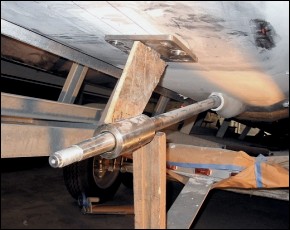
With our rudder log/lower bearing in place, we can now use our “dummy” shaft to reconfirm clearances, angles, etc., before moving on to our next step-the strut.
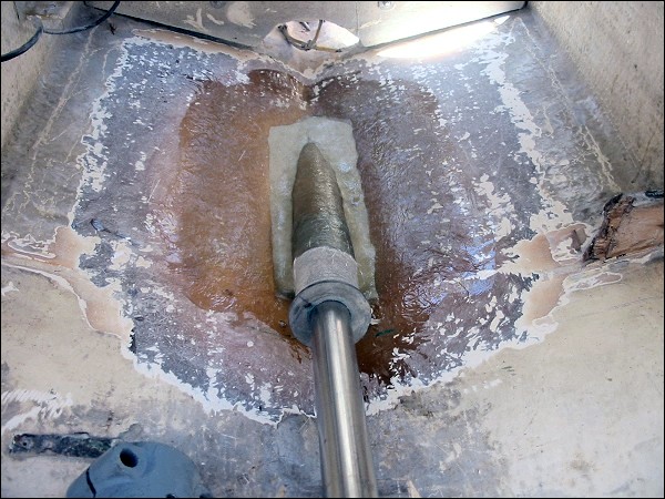
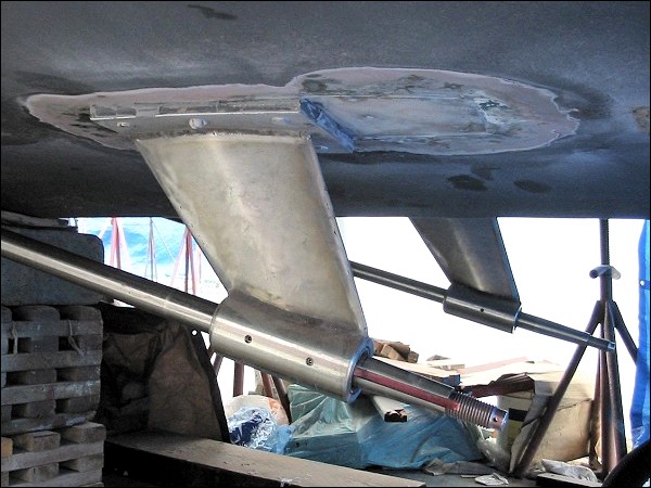
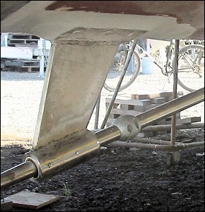
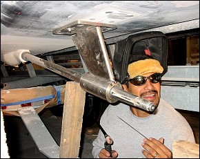
After the dummy shaft is close to EXACTLY where it needs to be, held on one end with the transmission/coupling, and a brace located just in front of where the strut will be, we slide up our fully machined stainless lower tube with a bearing or very accurately machined bushing inside of it.
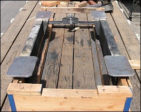
Some measuring, and we now have it in final resting position in perfect alignment as it’s on the shaft. Next comes some basic drawing and design of what we want this strut to be like (single leg, V-type, extra HD etc.) and then after that decision, we make the base plate. We temporarily screw it up to the boat in its correct position, and now design and fabricate the “leg” between the base and the heavy wall tube.
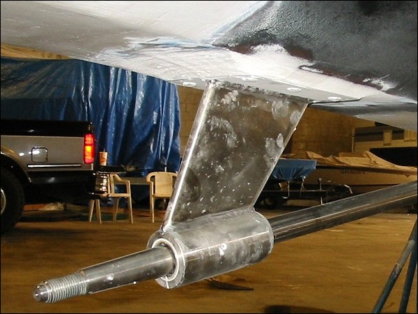
On single legged struts, we employ two methods of construction and this is dependent upon size and duty. Most common is a solid center leg made of ½” -1″ thick 316L stainless plate that has been cut and shaped to fit. This is usually what we do for props up to about 21″ diameter and 1.75″ shafts using close to minimum prop clearances. For heavier duty applications when we still want to use a single legged strut, we use a 3 piece leg tapered, curved and shaped to form a very strong somewhat diamond shaped cross section. This is the only way we feel we can get the strength needed for single legged fabricated struts using props up to 30″ diameter and sometimes bigger. In both cases we always “slot & key”, and weld the center leg to the base allowing for welding attachment form both sides. When the application requires a much heavier/stronger strut, then the “V-Strut” design comes into play.
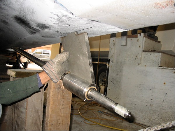
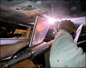
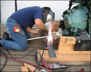
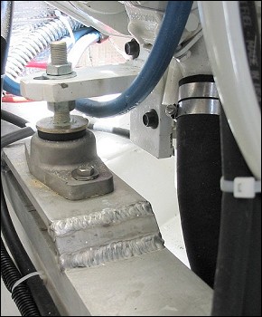
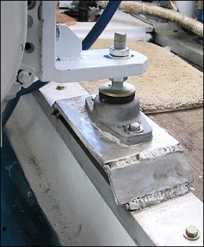
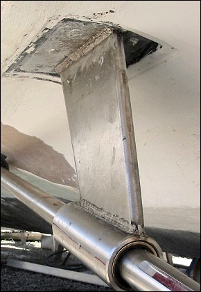
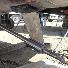
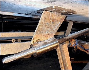
Back to “OUR” strut. All 3 pieces have now been made and it’s time for the “tack-up”. .A portable TIG makes life easy now, so we tack it up in place, take to the welding bench, and we weld it up so it becomes ONE. We already know that the final welding will distort it some from this exact shape/angle. No problem, as we are going to float our finished strut in place w/ epoxy to compensate for these types of imperfections.
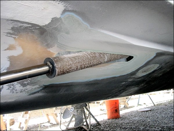
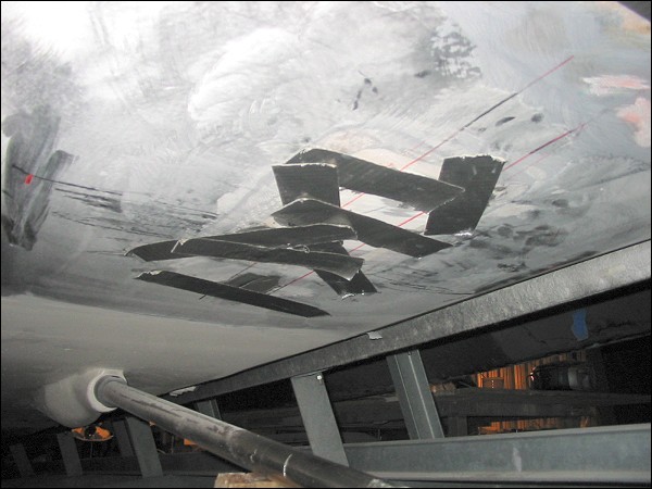
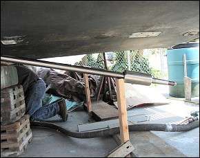
With our finished strut in hand, it’s back to the dummy shaft that is exactly where we want it. Some prepping on the hull, a pre-fit / slide-up of our new strut to see if when in position, it is not interfering with the hull.
Actually we do not even want it to touch, if possible-maybe 1/16″ to 1/8″ clearance all around, as this will make floating much easier. A few more checks and we mix up a cup or so of our favorite epoxy that is suited for this purpose-this is also a judgment call based upon the size of the fill, the base plate dimensions, ambient temps, and your experience as to what works for you. Gray “Marine Tex” will never let you down, although we don’t use it.. Our favorite of late are the “Simpson Strong-Tie” 2-part epoxies that come in “twin tubes”, having compression yields above 10,000 PSI. Most any high quality 100% solids epoxy non-sag paste sold thru industrial or marine outlets will do the job. Using West System, Systems III , or ??, will also work if used with hi-density fillers.
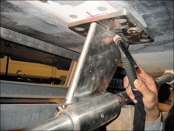
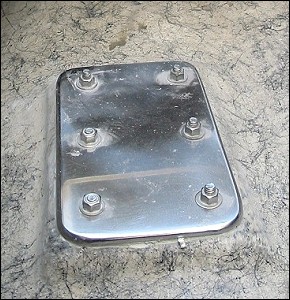
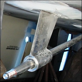
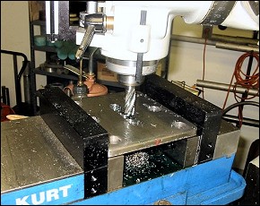
The strut has now had a 24 hour soak in it’s epoxy bed, so now it’s time to drill. We have planned well so we punch thru the hull w/ a drill 1/64″ larger than are bolt size — (always sloppy) as we want clearance for our sealant that will be used for bolt-up and backing plates. After drilling, we measure and fabricate an applicable backing plate (1 piece or 2 pieces), temporarily screw them in place, and mark them for final drilling. Backing plate material can be a thick section of fiberglass, Stainless or bronze. If SS (our preferred choice) usually 3/16″ to 1/4″ is more than sufficient. Lots of 5200 or other type of underwater sealant is what you do not want to skimp on when doing the final bolt up-We are looking for a 100% fill/bed of the bolts and backing plates.
We now install the bearing(s) permanently. Our own SOP for this is “NEVER” install a bearing that will not slide easily into the strut, stern casting, shaft tube, etc.. It’s just “our thing”, and we always machine as needed for a “slide” fit-maybe .015 to .020″ clearance for a bearing OD of 2″ to 3″. Slide the bearing in, mark for set screw drillings, remove and drill full depth/diameter for these, refit the bearings, put in set screws and seat lightly, but then back off ½ turn or so – and now you have a MECHANICAL interlock that will never fail or distort the bearing shell – remove for the last time, coat w/ 5200 or a thinner epoxy, slide in, remove excess – add sealant to the set screws, seat lightly, then back off ½ turn – and voila-you now have a “floated” bearing that will not do anything stupid. Many times we will machine the “bore” of our strut or machine .060″ to .125″ off the bearing OD to allow a “Full” float of the shell. This will allow a more perfect bearing to shaft alignment to compensate for other types of misalignments we find doing this type of work. We install the bearing with lots of epoxy and the set screws holding it, but allowing it to wiggle as needed, slide in the shaft, and let it cure as a shaft holding the bearing in perfect alignment. Many repowers that have poorly aligned struts and fixed shafts logs need this type of “realignment”. Of course, your next question is how do your remove a “glued-in” bearing – simple, same as normal-the right tools and techniques sometimes using a small of heat.
Shaft Log
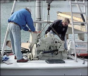
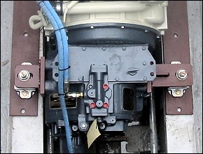
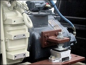
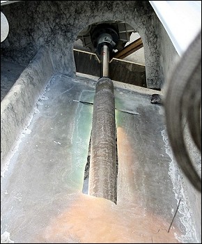
With the strut & bearing in place “permanently”, our shaft is now finished machined to the exact length with the coupling installed. Back to the vessel and we now do a “feeler gauge” alignment between the engine and shaft. With that done, we now move to permanently install the shaft log using the shaft to hold it in place or, to “Float” it in place. Many times we use the log tube to become our intermediate strut. Simple, strong and practical. Using an “intermediate” or mid-bearing, is based upon shaft to diameter length, application and past experience. You typically want to keep your intermediate bearing at least 20 (30 is better) shaft diameters behind the transmission output flange on flexible mounted engines to allow for some un-strained movement that all boat/engines have. If installing a cast bronze shaft log, we still use this technique of letting the shaft hold the log in place while aligning / fitting / attaching.
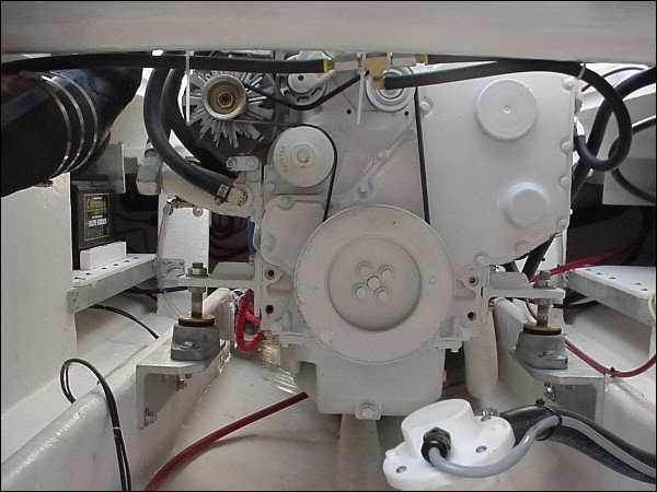
With our log now installed in perfect alignment, we do some finishing touches like drilling for water flow in front of our “mid-bearing”, some finish gel coat, etc.. We install our packing gland of choice, and now move to finishing all 4 engine mounts/rails that will allow us to finally install our engine. During all of this work, our transmission was the key piece of this puzzle, kinda like a corner stone, and will now be used to finalize the rest of the engine mounting brackets, etc.
Since our shaft is now in place, we recheck for “feeler gage” alignment, and have the option now of actually drilling our transmission isolator to stringer brackets connection. After all, we have perfect alignment, that shaft is in position, so there is no reason not to. Certainly easier as everything is easy to get to as we still have not lifted in the engine. And, we also know that when the engine is installed, its weight will compress the rear isolators some (maybe 1/8″ or so) , but we compensated for that when we designed and set our transmission bracketing in place – right??
Engine Mounts
Back to installing our crankshaft jig, getting out the drawing and designing your front engine mounting “system”. I used the term “system” as there are so many options that each vessel might require to make the engine package fit RIGHT. We have gone this far and really need to think about the front mounting as a “system” and not just something that the front of the engine sits on. Typical mistakes that are made here is thinking that the engine brackets that came on the front of the engine must be used. This could not be further from the truth.. In fact, in probably 75% of the repowers we do, the front brackets that were supplied by the engine manufacturer are wholly inadequate in design to allow what we feel is a proper installation. They may or may not be at the best C~C distance for this install. They are more than likely not at the height for the install. And, they may not be in the best fore and aft position either. Of course, the weak at heart, or less informed individual, may come back and say “that’s what was designed and you cannot modify it” – HORSE MANURE – You either believe in your own work, or you shouldn’t be doing it in the first place.
Redesigning front engine brackets to allow the best combination of fit and best alignment to the structure of the individual vessel cannot be done by the engine manufacturer on a drawing board 2000 miles away. Every vessel is different. It’s just about always easier to re-design the front brackets than to re-design the boat. If the supplied front brackets happen to be a good compromise as to their location and just happen to “fit” where they should, then by all means, use them.
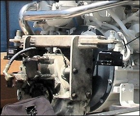
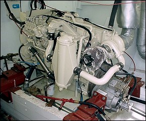
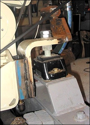
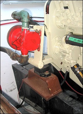
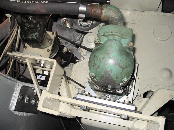
I’ll mention a case in point here – Since the Cummins B is a very popular engine used for repowers, I will mention that the standard front mounts, although nicely made, interfere with the R&R of the seawater pump in their normal position. By using a totally different front bracket, or by adding a spacer behind them, of ¼” to ¾”, you will accomplish at least two things. One, you can increase your C~C distance from approx 22.5″ to something wider ( like 23-24″ C~C). And now you will be able to R&R your seawater pump without lifting the engine and removing the bracket first. When we use this “stock” bracket, we like adding a ½” to ¾” spacer, and increasing the bolt length accordingly. There are NO engineering issues here as to loads, strengths, etc., as long as the new bolts chosen are of a 8.8 or better quality, and things are put together right, and tight.
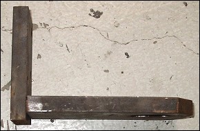
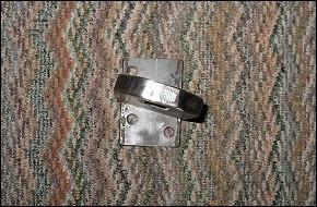
Another important part of the front mounting “system” that would be done now is whether you may have an additional belt driven accessory, like a second alternator or hydraulic pump. This is best done at this time as it usually can be designed as part of the front bracket assembly. All accessory drives should be part of the engine so as to “move” with it, and many times the only place to bolt heavy bracketing to an engine is where the front mounting brackets are. The list of pictures here shows just a few of the many types of modifications that needed to be made to the factory front brackets to allow the proper fit in the vessel.
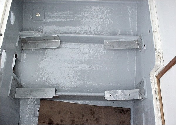
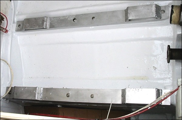
Well, by now we have made our decision as to front bracketing, so now it’s time for the stringer end of the front mounts. Again, we prefer using aluminum extrusions whenever possible and “float” them in the right place for perfect alignment-we then thru bolt as needed. We keep a variety of Aluminum extrusions (6061-T6 structural angle) in stock and we find that 4×6 thru 8×8 with thickness from 3/8″ to 3/4″ will cover 99+% of all the install we’ve see. 12″ long seems to always give more that enough support while still allowing small adjustments in placement due to last minute changes. Three to four well placed bolts from 3/8″ to 1/2″ diameter with backing plates to spread loads over a wide area always keep things secure.
If we look where we are now, you can see that the entire mounting system and drive train was designed and built without lifting in the engine. Good job. We had all that space to work and plan and we have far fewer bleeding knuckles to prove it.
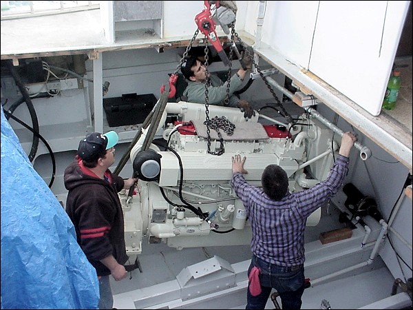
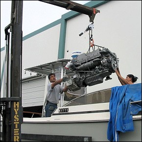
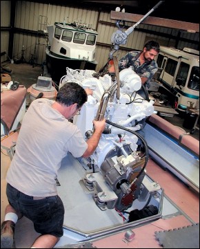
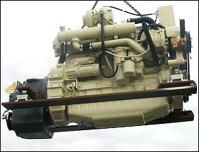
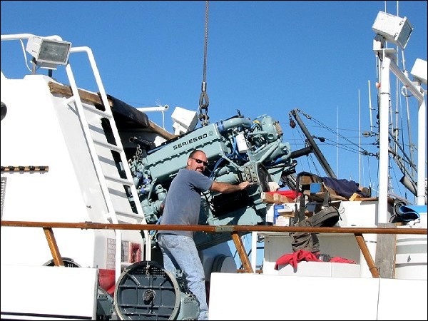
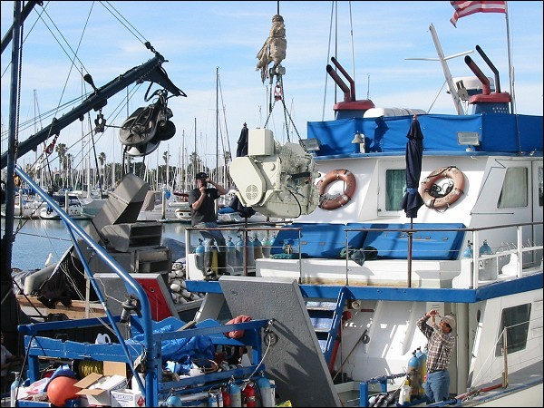
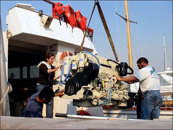
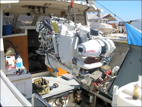
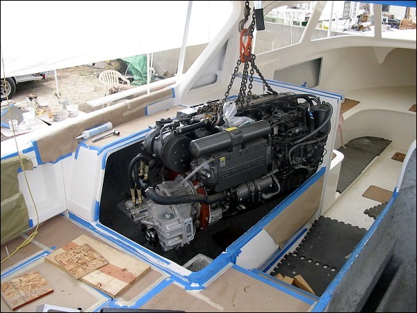
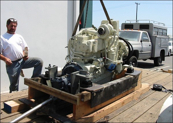
Lift In
We’ve come a long ways now and we deserve our next step. Typically you would now remove the transmission from the vessel and install it permanently on the engine. Do as much as you can at this point, like trans oil lines, oil drain lines, added sending units for special gages, oil for the engine and trans, cable bracketing, etc.. It’s always easier if these things can be done BEFORE lift-in, especially in tight engine rooms. Lifting in the engine is next and it always seems to inspire a sense of accomplishment as when she goes in, it fits like a glove and our initial pre-alignment now is a simple task. Remember those isolation mount holes we drilled?? Well as the engine comes down, a little wiggling and a small push, drop in a bolt on the first rear isolator that touches, and it pins the package in place for the other side. I forgot to mention that good planning for the lift, would be to “look” at your mounts in relation to “Mother Earth”, and what ever relative angle they are at, you should pre-adjust your lifting apparatus to allow the engine to lift at that angle or slightly more. This allows the rear pre-drilled isolators to hit the stringer brackets first.
Since we did our homework well, followed good design practices, our fabrication and assembly practices were done with care, AND we used some imagination during the entire process to make everything look politically correct as if it were a “factory” job, the actual lift-in goes as smooth as silk. Let’s pat ourselves on the back for a job well done!